External ultrasonic level gauge with sound velocity self-calibration function and measuring method thereof

An ultrasonic and self-calibration technology, which is applied in the direction of liquid/fluid solid measurement, measuring devices, liquid level indicators, etc., can solve the problem of low measurement accuracy, low liquid level measurement accuracy, and measurement accuracy less than 1mm level, etc. problems, to achieve the effect of reducing environmental interference, stable and accurate measurement results

Active Publication Date: 2014-07-09
XIAN HUASHUN MEASURING EQUIP
View PDF6 Cites 25 Cited by
  • Summary
  • Abstract
  • Description
  • Claims
  • Application Information

AI Technical Summary

Problems solved by technology

The measurement principle of ultrasonic liquid level gauge is simple. The main factor affecting its measurement accuracy is the reference sound velocity value in liquid level calculation. The sound velocity value is related to the measured medium, temperature, pressure and other factors. The complex and changing working conditions directly affect the reference sound velocity. measurement, which leads to low accuracy of liquid level measurement
At present, the measurement accuracy of most ultrasonic liquid level gauges is not high, and some applications with high requirements cannot be satisfied, and the measurement accuracy cannot reach the order of 1mm. The main reason is that the reference sound velocity measurement error of the ultrasonic liquid level gauge is relatively large. Indirectly lead to low accuracy of liquid level measurement

Method used


Image

  • External ultrasonic level gauge with sound velocity self-calibration function and measuring method thereof
  • External ultrasonic level gauge with sound velocity self-calibration function and measuring method thereof

Examples


Embodiment Construction

[0021] The present invention will be described in further detail below in conjunction with the accompanying drawings.

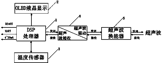
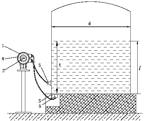
[0022] see figure 1 , 2 , an external ultrasonic liquid level gauge with sound velocity self-calibration function, including DSP processor 1 connected to OLED display 2, DSP processor 1 connected to temperature sensor 3, temperature sensor 3 connected to the measured storage tank, DSP processor 1 It is connected with the ultrasonic driving and receiving module 4, and the ultrasonic driving and receiving module 4 is connected with the storage tank under test through the ultrasonic transducer 5.

[0023] There are two ultrasonic transducers 5 , one is a measuring probe for sending and receiving ultrasonic waves, and the other is a calibration probe for self-calibrating reference sound velocity. The invention adopts a liquid-mediated installation and measurement method, which can effectively reduce environmental interference, and can modify ultrasonic emission...


PUM


Abstract

The invention discloses an external ultrasonic level gauge with a sound velocity self-calibration function. A DSP and an OLED display screen are connected with a temperature sensor, the DSP is connected with an ultrasonic driving and receiving module, and the ultrasonic driving and receiving module is connected with a storage tank to be detected through an ultrasonic transducer. The measuring method includes the steps that (1), a measuring probe and a self-calibration probe are externally attached to the bottom and the wall of a tank body to be detected respectively; (2), the DSP is started, the ultrasonic level gauge is in a double-probe measuring mode, reference sound velocity is directly calibrated through the self-calibration probe, or the reference sound velocity is indirectly calibrated by using a temperature and sound velocity data table; (3), after the speed velocity is calibrated, a blind area position is detected; (4), an ADC module is used for collecting an ultrasonic signal to obtain wave backing data of the medium to be detected, and round tip time of ultrasonic wave transmission is calculated; (5), according to the reference speed velocity and the transmission time, the height of the liquid level is calculated; (6), a calculated liquid level value is used for stabilizing the liquid level; (7), the display result and 4 mA-20 mA output of the liquid level of the OLED display screen are updated, and the latest liquid level value is stored in FLASH.

Description

technical field [0001] The invention belongs to the technical field of storage tank liquid level measurement, and in particular relates to an external ultrasonic liquid level gauge with a sound velocity self-calibration function and a measurement method thereof, which utilizes ultrasonic technology to be externally placed outside a storage tank to realize accurate liquid level measurement. Background technique [0002] At present, ultrasonic technology is widely used. Through the comparison of existing ultrasonic liquid level gauges, the external ultrasonic liquid level gauge is easy to install and does not need to open the tank to be tested, and does not need to contact corrosive, toxic, viscous, etc. The medium can truly realize non-contact measurement, and the ultrasonic wave propagates in the liquid medium with less interference, which can meet the application requirements of more occasions. The measurement principle of ultrasonic liquid level gauge is simple. The main f...

Claims


Application Information

Patent Timeline
IPC IPC(8): G01F23/296
Inventor 李斌李赤文高新岗
Owner XIAN HUASHUN MEASURING EQUIP
Why Eureka
Try Eureka