
Tension-torsion composite clamp under multi-physics coupling condition

A multi-physics and fixture technology, applied in the direction of applying stable tension/pressure to test the strength of materials, instruments, measuring devices, etc., can solve the problems of unusable testing, testing material mechanical properties, low cost, etc., to achieve reliable work, Strong practicability and simple operation

Active Publication Date: 2014-07-09
JILIN UNIV
View PDF10 Cites 11 Cited by
  • Summary
  • Abstract
  • Description
  • Claims
  • Application Information

AI Technical Summary

Problems solved by technology

Common test fixtures are mechanical and hydraulic. Mechanical fixtures provide tension through self-locking wedges or provide torque through threaded clamping. This type of fixture has a simple structure and low cost, but it cannot be used for fatigue testing, nor can it be used for Testing under Multiphysics Coupling Conditions
The hydraulic fixture directly tightens the specimen through wedges to provide tensile force, and can also be improved for tensile and torsion composite tests, but it cannot be used to test the mechanical properties of materials under multi-physics field coupling conditions such as temperature field, magnetic field, and electric field.

Method used


Image

  • Tension-torsion composite clamp under multi-physics coupling condition
  • Tension-torsion composite clamp under multi-physics coupling condition
  • Tension-torsion composite clamp under multi-physics coupling condition

Examples


Embodiment Construction

[0019] The detailed content of the present invention and its specific implementation will be further described below in conjunction with the accompanying drawings.

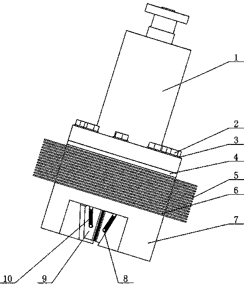
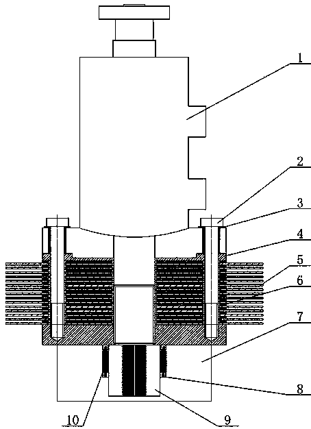
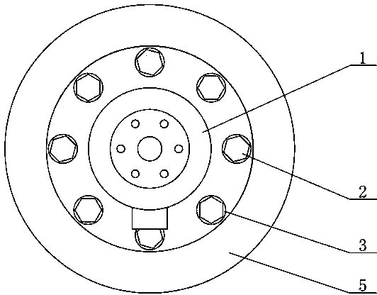
[0020] see Figure 1 to Figure 6 As shown, the tension-twist compound clamp applicable to multi-physical field coupling conditions of the present invention includes a constant velocity hydraulic cylinder 1, an insulating part, a heat insulating part, and a clamping part. The rear end of the constant velocity hydraulic cylinder 1 passes through the The flange is connected with the tensile torsion composite sensor and installed on the testing machine. The rear end of the flange is a stepped shaft, leaving a wrench space for screw assembly; the constant velocity hydraulic cylinder 1 is installed on the positioning piece 4 through the front flange branch, and the positioning piece 4. Next to the heat insulation part, the lower part of the heat insulation part is the clamping part; the front flange of the constant velo...


PUM


Abstract

The invention relates to a tension-torsion composite clamp under a multi-physics coupling condition, and relates to the technical field of material tests. The rear end of a constant speed hydraulic cylinder is connected with a tension-torsion composite sensor, and the end surface of a piston rod on the front end of the constant speed hydraulic cylinder is coated with a high-temperature ceramic insulating material; a heat insulation part comprises a connecting screw and a rubber insulating mat and is composed of mica sheets and copper sheets in an overlaying manner; the clamp is used for connecting a front-end flange, a positioning piece, the heat insulation part and a clamping part of the constant speed hydraulic cylinder together through bolts, and a wedge block is used for clamping a test specimen under the thrust action of the constant speed hydraulic cylinder; a spline pair is arranged between the front end of the piston rod and a clamp body, and is used for preventing relative rotation of the piston rod and the clamp body and transmitting torque. The tension-torsion composite clamp provided by the invention can be applied to a tension-torsion composite material testing machine with loading modules of temperature fields, electric fields, magnetic fields and the like, and the material testing machine can test the mechanical property of a material approaching to a serving condition under a multi-physics coupling condition and under the simultaneous effect of tension and torsion loads. The tension-torsion composite clamp has the characteristics that the operation is reliable, and the operation is simple.

Description

technical field [0001] The invention relates to a tension-twist composite fixture which can be used under multi-physics field coupling conditions, which is used in the technical field of material testing, so that the tension-twist composite material testing machine can be used in tension under multi-physics field coupling conditions such as temperature field, electric field, and magnetic field. Under the simultaneous action of tensile and torsional loads, testing the mechanical properties of materials close to service conditions has great significance and good application prospects for avoiding material failure in the engineering field. Background technique [0002] In the field of engineering, materials are usually served under compound loads, such as under the compound action of tension and torque; at the same time, the properties of materials will be affected by temperature fields, magnetic fields, electric fields, etc., for example, the yield strength of materials decreas...

Claims


Application Information

Patent Timeline
Patent Type & Authority Applications(China)
IPC IPC(8): G01N3/04G01N3/10G01N3/26
Inventor 赵宏伟李建平张攀峰任露泉唐可洪范尊强张富黄虎董晓龙高景
Owner JILIN UNIV
Learn More