Experimental device of split hopkinson pressure bar based on electromagnetic force load

A technology of Hopkinson pressure bar and experimental device, which is applied in the direction of applying stable tension/pressure to test the strength of materials, etc., which can solve the problems of inability to realize low strain rate experiments, difficult control of incident wave amplitude, and limited strain range. Achieve precise control, simple operation and good repeatability

Active Publication Date: 2014-07-09
NORTHWESTERN POLYTECHNICAL UNIV
View PDF3 Cites 53 Cited by
  • Summary
  • Abstract
  • Description
  • Claims
  • Application Information

AI Technical Summary

Problems solved by technology

[0005] In order to overcome the shortcomings of the prior art that the amplitude of the incident wave is difficult to control, the operation is cumbersome, the strain range is limited, and some low strain rate experiments cannot be realized, the present invention proposes a separate Hopkinson pressure rod based on electromagnetic force loading experimental device

Method used


Image

  • Experimental device of split hopkinson pressure bar based on electromagnetic force load
  • Experimental device of split hopkinson pressure bar based on electromagnetic force load
  • Experimental device of split hopkinson pressure bar based on electromagnetic force load

Examples


Embodiment 1

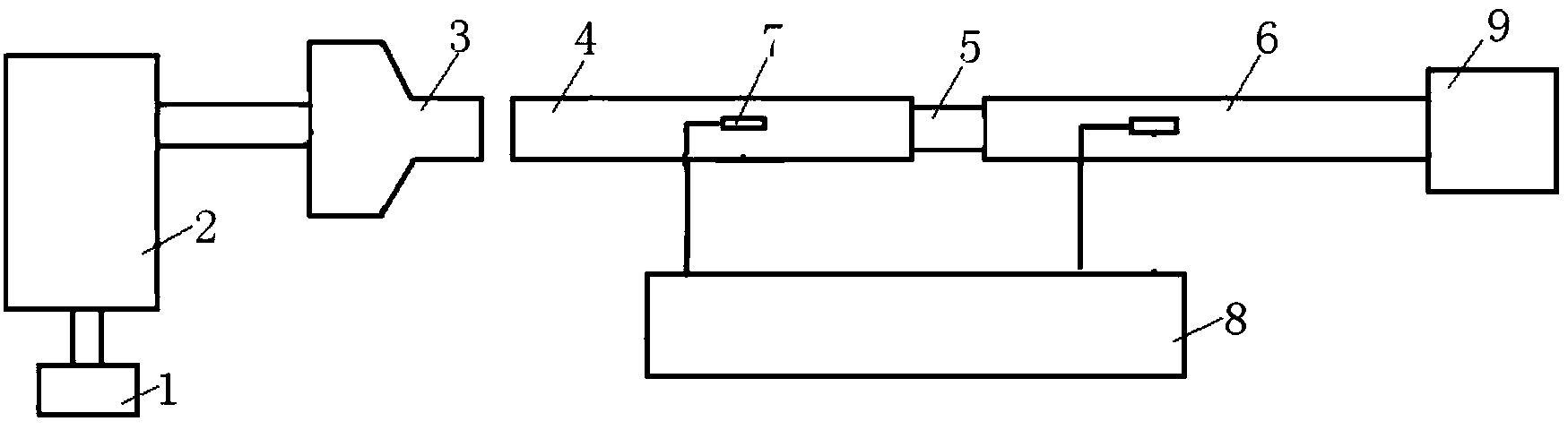
[0022] As shown in the figure, this embodiment includes an electromagnetic riveting device and a separate Hopkinson pressure bar experimental device. The electromagnetic riveting gun 3 of the electromagnetic riveting device is located at one end of the incident rod 4 of the separated Hopkinson pressure bar experimental device, and The spring between the secondary coil and the primary coil is removed, so that the secondary coil and the primary coil are naturally fitted to ensure that there is no prestress in the incident rod before the stress wave is generated. The small end of the tapered head of the electromagnetic riveting gun 3 on the electromagnetic riveting device is fully contacted with the incident end face of the incident rod 4 , and the electromagnetic riveting gun 3 is coaxial with the incident rod 4 .

[0023] The electromagnetic riveting device 2 adopts the low-voltage electromagnetic riveting device disclosed in the utility model patent publication number CN2865927...


PUM


Abstract

The invention discloses an experimental device of a split hopkinson pressure bar based on electromagnetic force load. The experimental device comprises an electromagnetic riveting device and a split hopkinson pressure bar experiment device, wherein the electromagnetic riveting device is arranged at one end of an incident bar of the split hopkinson pressure bar experiment device; the end face of an electromagnetic riveting gun on the electromagnetic riveting device is in full contact with the end face of the end of the incident bar, so that the electromagnetic riveting device can generate stress pulse which is directly input into the incident bar and generated pulse signals can be accurately controlled. By adopting the experimental device, the split hopkinson pressure bar is not greatly improved; the electromagnetic riveting device is only used for replacing an air gun in a conventional split hopkinson pressure bar system; accurate control of stress wave is achieved in an electromagnetic way; meanwhile, the width of the stress wave generated by the electromagnetic load is not limited by the length of an impacting bar, so that the width of the stress wave generated by the experimental device is large enough at a high strain rate, thereby achieving the normalization of experimental technologies of the split hopkinson pressure bar.

Description

technical field [0001] The invention relates to a device for testing the dynamic mechanical properties of materials, in particular to a separate Hopkinson pressure bar experimental device based on electromagnetic force loading. Background technique [0002] Currently, the split Hopkinson bar technique is most widely used in the field of materials science to measure the mechanical properties of materials at high strain rates. The basic principle of this method is that a short sample is placed between two compression rods, and the sample is loaded by an accelerated mass, an acceleration pulse generated by the impact of the short rod or an explosion. At the same time, the pulse signal is recorded by using the strain gauge which is glued to the pressure rod and has a certain distance from the end of the rod. If the compression rod remains elastic, the stress pulse in the rod will propagate without distortion at the elastic wave speed. In this way, the strain gauge attached to ...

Claims


Application Information

Patent Timeline
Patent Type & Authority Applications(China)
IPC IPC(8): G01N3/08
Inventor 李玉龙聂海亮汤忠斌索涛吴蓓蓓
Owner NORTHWESTERN POLYTECHNICAL UNIV
Why Eureka
Try Eureka