Magnification display device and system
A display device and display system technology, applied in optical components, optics, instruments, etc., can solve problems such as high cost, difficult commercialization, and technical complexity, and achieve low cost, easy productization, and simple manufacturing process.
- Summary
- Abstract
- Description
- Claims
- Application Information
AI Technical Summary
Problems solved by technology
Method used
Image

Examples
Embodiment 1
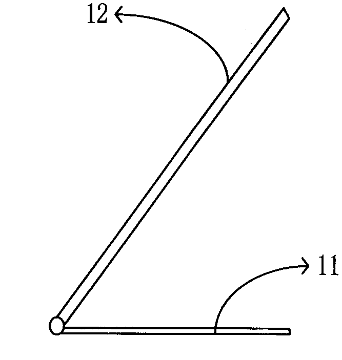
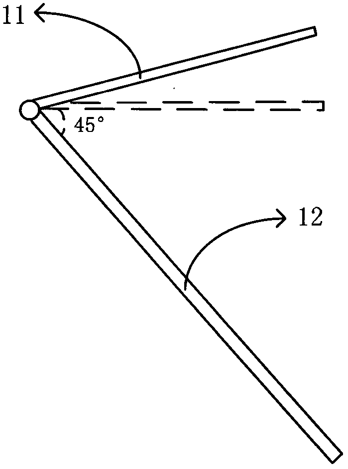
[0040] The present invention provides an augmented display device, such as figure 1 As shown, it includes a support body 11 and a transflective device 12 for placing an electronic display device. The support body 11 and the transflective device 12 form a connection with an angle of less than 90 degrees. The transflective device 12 converts the image of the electronic display device Amplified display.
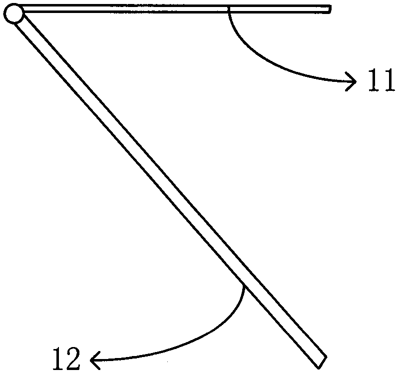
[0041] Wherein, the support body 11 can be as figure 1 Arranged under the transflective device 12 , the support body 11 can place the electronic display device on the one hand, and support the transflective device 12 on the other hand. The user places the electronic display device on the support body 11, and can see the image behind the transflective device. The support body 11 can also be as figure 2 It is arranged above the transflective device 12 for placing electronic display equipment. When in use, the amplified display device can be supported by an external support ...
Embodiment 2
[0048] An amplified display device, a support body 11, a transflective device 12 and an active connection structure (not shown in the figure), the support body 11 includes an accommodating structure 41 and a supporting structure 42, the accommodating structure 41 is used to accommodate the electronic display device, and the transmissive The reflective device 12 includes a connecting end 31 and a free end 32 opposite to the connecting end 31, and the transflective device 12 further includes a first surface and a second surface opposite to the first surface, the second surface 34 faces the accommodating structure 41, and the transmissive The connecting end 31 of the reflective device 12 is movably connected with the support structure 42 through the movable connection structure, and when the display device is amplified, the image displayed by the electronic display device is formed on the second surface side of the transflective device 12 after passing through the transflective dev...
Embodiment 3
[0057] An augmented display device, which differs from Embodiment 1 and Embodiment 2 in that the electronic display device can display naked-eye stereoscopic images. The augmented display device further includes a first image processing unit 20 configured to mirror the image displayed by the electronic display device along the horizontal central axis. Specifically, assuming that the number of pixels in the horizontal direction of each image on the display screen of the electronic display device is W, then the pixel value of any pixel point A (Xa, Ya) in each image is compared with the pixel point B (W- The pixel values of Xa, Ya) are swapped. From Figure 7a~7b It can be seen from the optical path diagram in that, due to the imaging effect of the transmissive mirror 105, the positions of the image points E and F without the transmissive reflective mirror 105 and the positions of the image points E' and F' after the transmissive reflective mirror are placed occur in the hori...
PUM
 Abstract
Description
Claims
Application Information
 - R&D
- Intellectual Property
- Life Sciences
- Materials
- Tech Scout
- Unparalleled Data Quality
- Higher Quality Content
- 60% Fewer Hallucinations
Browse by: Latest US Patents, China's latest patents, Technical Efficacy Thesaurus, Application Domain, Technology Topic, Popular Technical Reports.
© 2025 PatSnap. All rights reserved.Legal|Privacy policy|Modern Slavery Act Transparency Statement|Sitemap|About US| Contact US: help@patsnap.com