
Piezoelectric vibration generating set

A power generation device, piezoelectric vibration technology, applied in the direction of generator/motor, piezoelectric effect/electrostrictive or magnetostrictive motor, electrical components, etc., can solve the problem of low output efficiency, high resonance frequency, and not too thick Thin and other problems, to achieve the effect of large vibration amplitude, low vibration frequency and high power generation efficiency

Inactive Publication Date: 2014-07-09
BEIJING JIAYUE TONGLEJI ELECTRONICS
View PDF6 Cites 9 Cited by
  • Summary
  • Abstract
  • Description
  • Claims
  • Application Information

AI Technical Summary

Problems solved by technology

[0002] With the rapid development and application of micro-electromechanical system (MEMS) technology, it has driven the development of wireless sensor network technology. Among them, commercial applications have gradually been realized in the fields of industry, aerospace, communication, commerce, consumption and military affairs, which is a very serious problem. The most important problem is how to ensure the power supply of these wireless sensing units. The more popular method in traditional industries is to use batteries. Due to the large number of unit devices that make up the wireless sensor network and system, the size is small, and the location is scattered, this requires its power supply devices. It has the characteristics of small size, high efficiency, easy integration, unattended and unattended, etc. The use of traditional batteries can no longer meet the development requirements of wireless sensor networks and systems
For this reason, U.S. Patent US20070284969 discloses a piezoelectric vibration power generation device, which uses a gravity block arranged at one end to bend a flat plate, and the PZT laid on the surface of the flat plate generates electric energy due to bending deformation. The deformation of the cantilever beam is related to the length and thickness of the rod. Due to the limitation of structure and cost, the cantilever beam cannot be too long and the thickness cannot be too thin, which limits its displacement and PZT deformation, thus limiting its power generation efficiency. The longer the length, the worse the anti-shock effect. Therefore, in order to meet the output requirements, the rod should be as short as possible. In this way, the resonance frequency is high. Therefore, the deformation of the PZT set in this device is small, the resonance frequency is high, and the output efficiency is low.
Chinese patent application number 200810023882 also discloses a piezoelectric vibration power generation device, which also uses PZT attached to the surface of the cantilever beam to generate electric energy due to deformation. This solution also has the disadvantages of small deformation and low output efficiency.

Method used


Image

  • Piezoelectric vibration generating set
  • Piezoelectric vibration generating set
  • Piezoelectric vibration generating set

Examples


Embodiment Construction

[0032] In order to describe the technical content, structural features, achieved goals and effects of the present invention in detail, the following will be described in detail in conjunction with the embodiments and accompanying drawings.

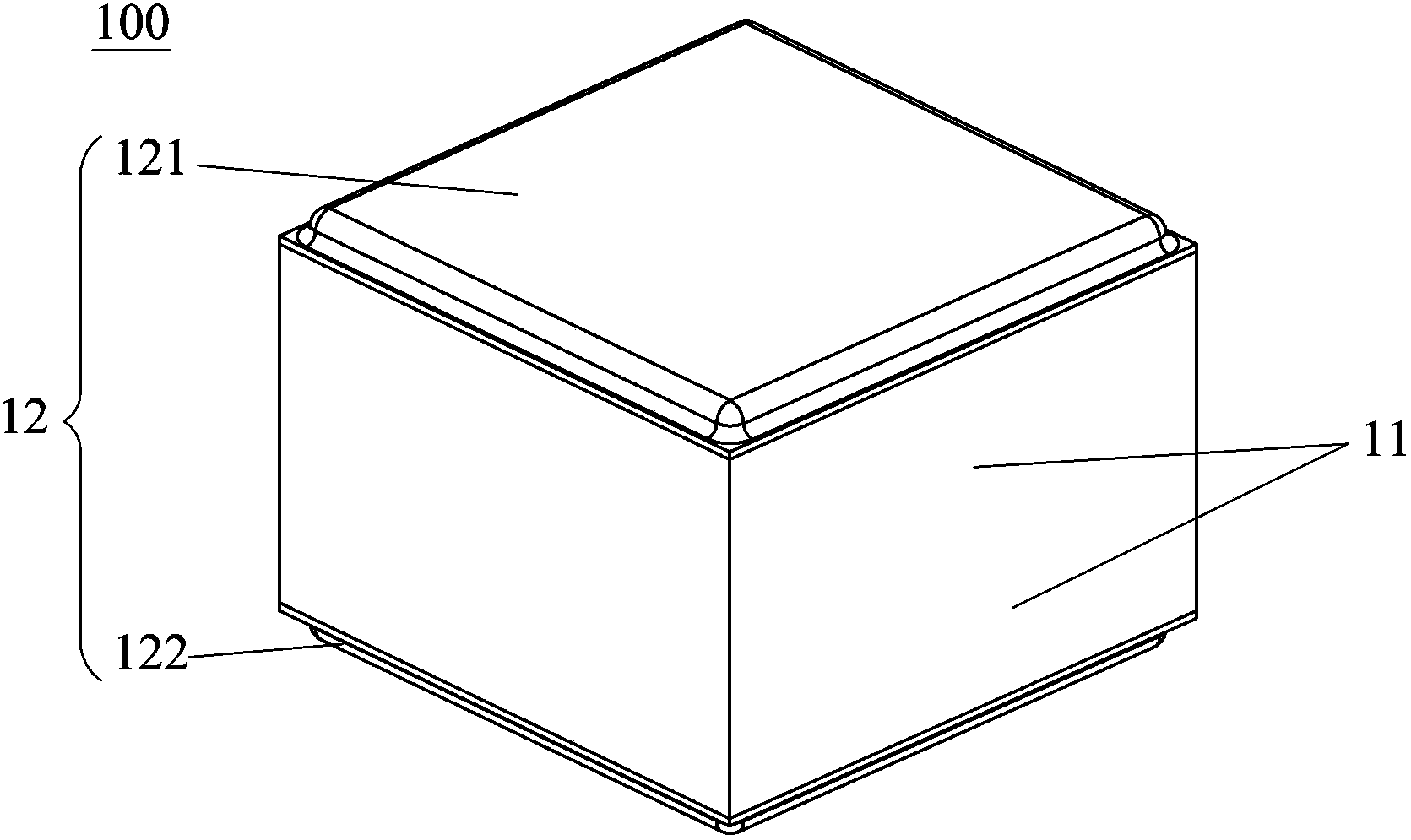
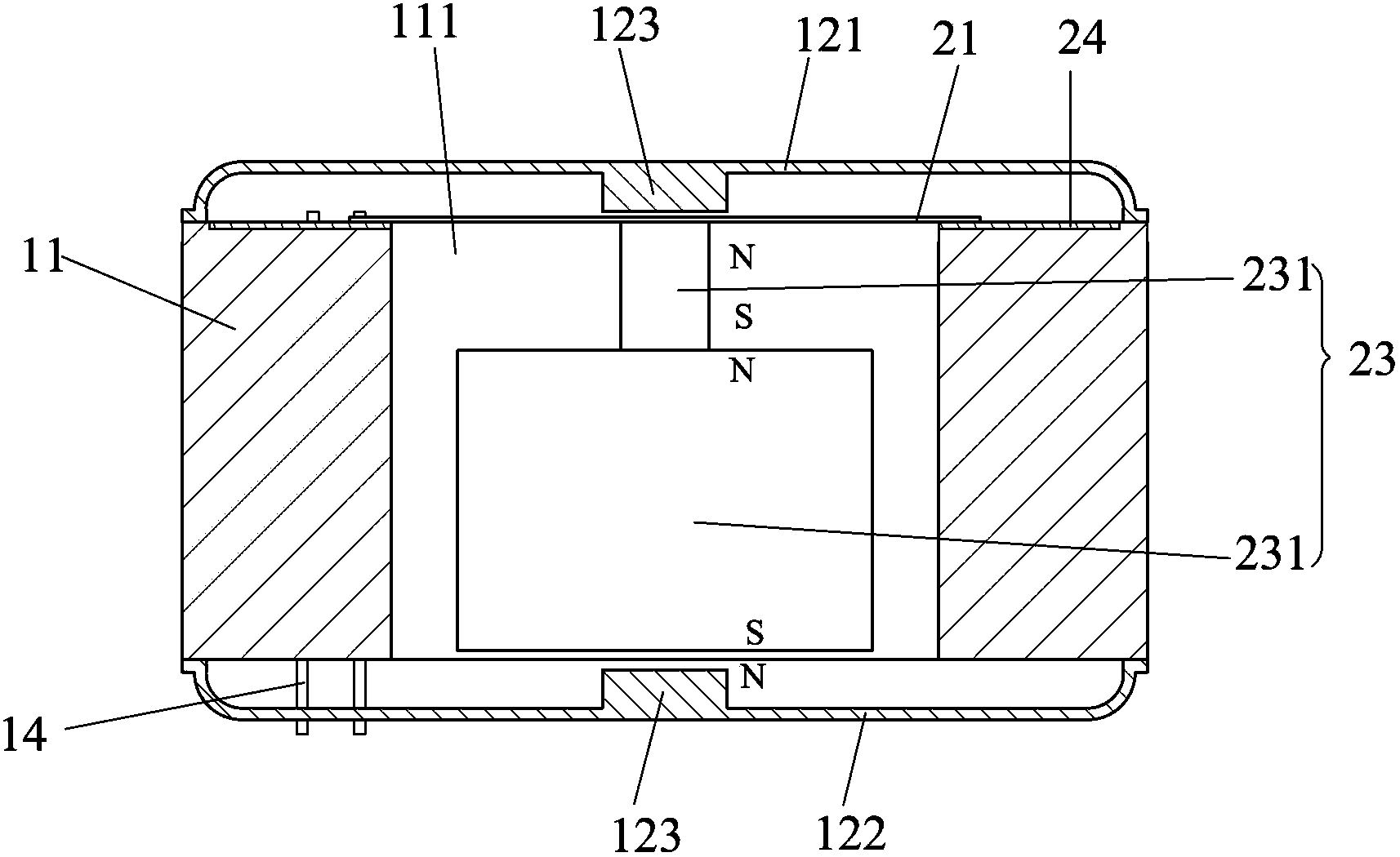
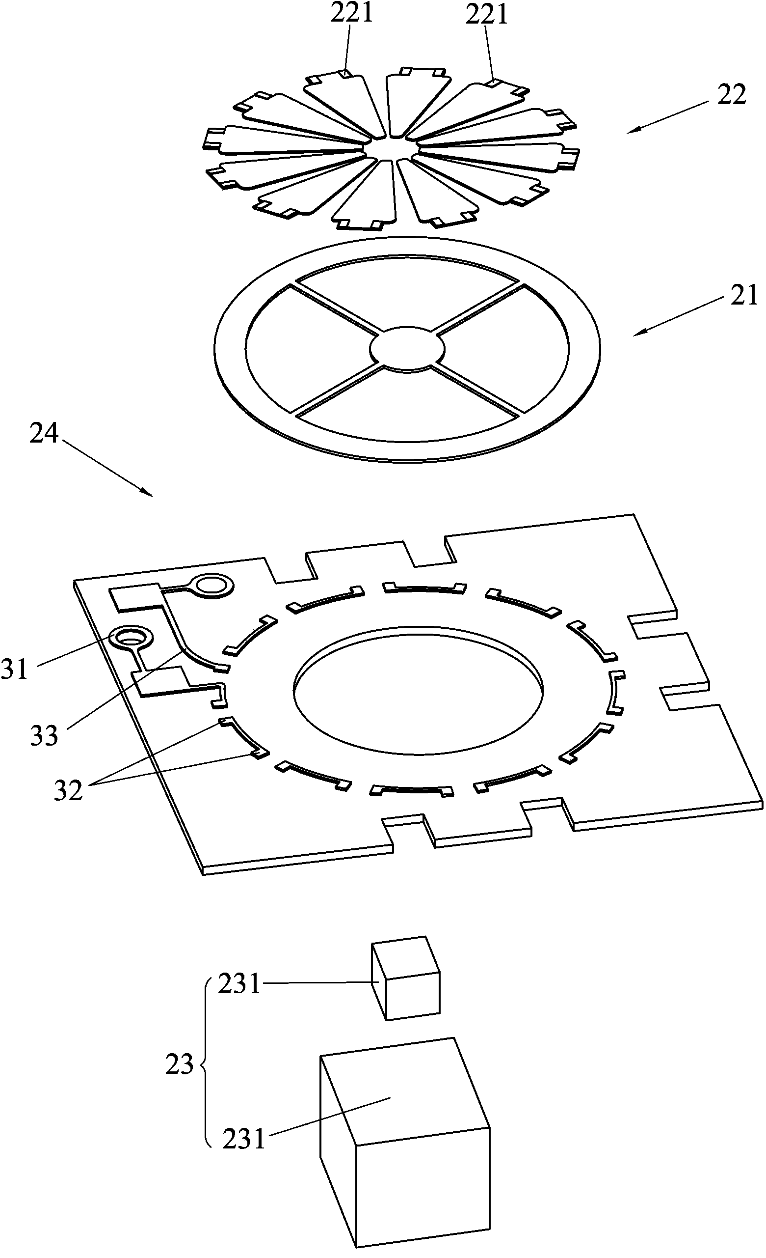
[0033] refer to Figure 1 to Figure 4a , the present invention discloses a piezoelectric vibration power generation device, the piezoelectric vibration power generation device 100 includes a base 11, at least two conductive solder pins 14 and at least one power generation component 13, the base 11 is a hollow structure; the At least two conductive solder pins 14 are installed on the base 11; the power generation component 13 includes an elastic plate 21, a piezoelectric sheet 22 arranged on the elastic plate 21 and a free Vibrator 23, the piezoelectric sheet 22 has at least two conductive layers, a piezoelectric layer sandwiched between the two conductive layers, and at least two pads 221, the pads 221 of the piezoelectric sheet 22 are con...


PUM


Abstract

The invention discloses a piezoelectric vibration generating set which comprises a base, at least two conductive welding pins and at least one generating component. The base is of a hollow structure, the at least two conductive welding pins are mounted on the base, each generating component comprises an elastic plate, a piezoelectric plate arranged on the elastic plate and a free vibrator mounted on the elastic plate, the piezoelectric plates are electrically connected with the conductive welding pins, each elastic plate comprises an annular edge supporting part which is supported on the base and a middle mounting part which is arranged inside the edge supporting part and located in the center of the corresponding elastic plate, a certain clearance is formed between each edge supporting part and the corresponding middle mounting part, and at least three connecting bridges enabling the edge supporting parts to be connected with the middle mounting parts are arranged in each clearance. The circumferential edges of the elastic plates are supported on the base, when the piezoelectric vibration generating set works, the elastic plates drive the piezoelectric plates to vibrate axially along the axes of the piezoelectric plates, and electricity generating efficiency is high.

Description

technical field [0001] The invention relates to the technical field of micro-nano electronics, in particular to a piezoelectric vibration power generation device. Background technique [0002] With the rapid development and application of micro-electromechanical system (MEMS) technology, the development of wireless sensor network technology has been driven. Among them, commercial applications have gradually been realized in the fields of industry, aerospace, communication, commerce, consumption and military affairs. The most important problem is how to ensure the power supply of these wireless sensing units. The more popular method in traditional industries is to use batteries. Due to the large number of unit devices that make up the wireless sensor network and system, the size is small, and the location is scattered, this requires its power supply devices. With the characteristics of small size, high efficiency, easy integration, unattended and unattended, the use of tradit...

Claims


Application Information

Patent Timeline
Patent Type & Authority Applications(China)
IPC IPC(8): H02N2/18
Inventor 冯淑兰彭春雷
Owner BEIJING JIAYUE TONGLEJI ELECTRONICS
Learn More