Differential phase contrast imaging with energy sensitive detection

一种差分相位、能量相关的技术,应用在生成经校正的差分相位图像数据,差分相位成像系统,校正差分相位图像数据领域

Active Publication Date: 2014-07-09
KONINKLIJKE PHILIPS NV
View PDF3 Cites 4 Cited by
  • Summary
  • Abstract
  • Description
  • Claims
  • Application Information

AI Technical Summary

Problems solved by technology

Especially in differential phase contrast tomography this can lead to strong capping artifacts in the reconstructed images

Method used


Image

  • Differential phase contrast imaging with energy sensitive detection
  • Differential phase contrast imaging with energy sensitive detection
  • Differential phase contrast imaging with energy sensitive detection

Examples


Embodiment Construction

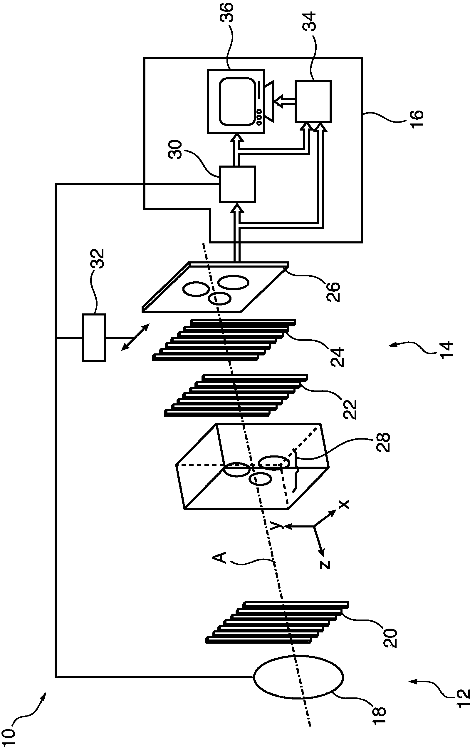
[0027] figure 1 A differential phase imaging system 10 with a radiation source 10 , a detector 12 and a controller 14 is schematically shown.

[0028] The radiation source 10 may include an incoherent X-ray source 16, such as an X-ray tube 18, and a source grating 20 for achieving spatial beam coherence. The radiation source 10 may be adapted to generate a spatially coherent beam of radiation.

[0029] The detector 12 may comprise a phase grating 22, an absorber grating 24 and an X-ray detector element 26 adapted to detect image data from X-rays radiated from said radiation source through an object of interest 28.

[0030] The source grating 20, the phase grating 22 and the absorber grating 24 have a plurality of equidistant X-ray absorbing (source and absorber grating) or phase shifting (phase grating) fringes perpendicular to the optical axis A of the imaging system 10. extending parallel to the direction.

[0031] The phase grating 22 acts as a phase-shifting beam splitt...


PUM


Abstract

For correcting differential phase image data 52, differential phase image data 52 acquired with radiation at different energy levels is received, wherein the differential phase image data 52 comprises pixels 60, each pixel 60 having a phase gradient value 62a, 62b, 62c for each energy level. After that an energy dependent behavior of phase gradient values 62a, 62b, 62c of a pixel 60 is determined and a corrected phase gradient value 68 for the pixel 60 is determined from the phase gradient values 62a, 62b, 62c of the pixel 60 and a model for the energy dependence of the phase gradient values 62a, 62b, 62c.

Description

technical field [0001] The present invention relates to differential phase contrast imaging. In particular, the present invention relates to a method for correcting differential phase image data, a method for generating corrected differential phase image data, a computer program, a computer readable medium and a differential phase imaging system. Background technique [0002] Radiography and tomography are important methods used in a variety of applications, such as non-destructive exploration of large samples, quality inspection of industrial products, and non-invasive inspection of anatomical structures and tissue regions of interest inside a patient's body . [0003] X-ray imaging based on attenuation of X-rays can yield excellent results where highly absorbing anatomical structures such as bone are embedded in tissue of relatively weakly absorbing material. This is due to the fact that the penetration depth of a hard X-ray beam can be quite high, which allows recording...

Claims


Application Information

Patent Timeline
Patent Type & Authority Applications(China)
IPC IPC(8): G06T5/50G06T11/00
CPCG06T5/50G06T11/005G06T2211/408G01N23/046G06T7/0014
Inventor T·克勒J-P·施洛姆卡
Owner KONINKLIJKE PHILIPS NV
Why Eureka
Try Eureka