
An automatic detection device

An automatic detection device and detection device technology, applied in the field of machinery, can solve the problems of large eye damage to workers, failure to provide details, slow time consumption, etc., and achieve the effects of low cost, convenient management, and improved detection efficiency

Active Publication Date: 2016-01-13
ZHEJIANG GREEN NEW MATERIALS
View PDF8 Cites 0 Cited by
  • Summary
  • Abstract
  • Description
  • Claims
  • Application Information

AI Technical Summary

Problems solved by technology

In the existing production line, inspection is generally done manually, which is not only time-consuming but also harmful to workers’ eyes.
[0003] Among the existing automatic detection equipment, for example, the Chinese patent "An automatic detection method for photovoltaic module quality" with the publication number CN103022219 discloses a general method for detecting cell cracks, that is, taking pictures with an infrared camera, comparing pictures, and providing software. Judgment results, the patent provides a more general detection method, but it fails to provide detailed details, such as how to load materials, how to unload materials, how to take photos, etc.
[0004] Another example is the Chinese patent with the publication number CN102878924 "Rotary disc type multi-station high-precision detection device based on multi-CCD and line laser", which discloses equipment such as a frame, a CCD detection device, a host computer, a servo motor, and a PLC controller. However, the loading and receiving of materials are still placed and collected manually. The qualified products and different types of unqualified products are only marked by the host computer, and cannot be picked and placed automatically. Therefore, strictly speaking, the automatic detection device involved in this patent is only semi-automatic. Detection device, still needs manual assistance

Method used


Image

  • An automatic detection device
  • An automatic detection device
  • An automatic detection device

Examples


Embodiment 1

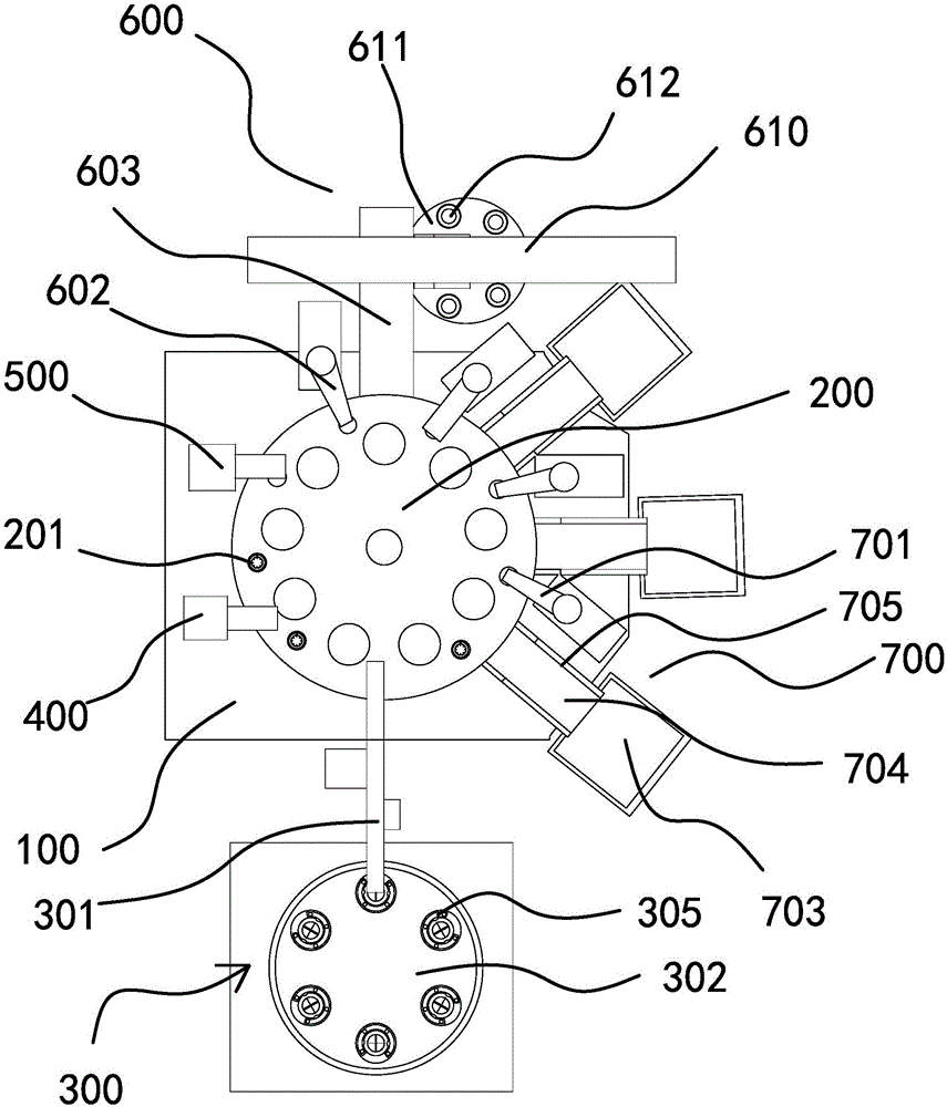
[0036] Such as figure 1 As shown, the automatic detection device includes a frame 100 and a turntable 200 arranged on the frame 100, and the frame 100 is provided with a feeding device 300, a first detection device 400, and a second detection device that surround the turntable 200 in turn. The device 500, the qualified product receiving device 600 and the defective product receiving device 700.

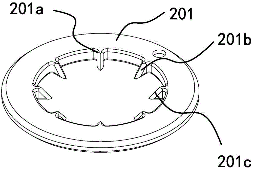
[0037] Such as figure 2 As shown, a plurality of uniformly distributed and annular reference plates 201 are installed on the turntable 200, a positioning block 201a is formed extending radially on the inner wall of the reference plate 201, and a positioning block 201a is formed at the outer end. From the upper surface of the reference plate 201 to the lower surface of the reference plate 201, the inclined portion 201b is gradually inclined downward. The inclined portion 201b is composed of a plane and two intersecting inclined surfaces, and the intersection of the two inclined surfa...

Embodiment 2

[0078] Such as Figure 13 As shown, the structure and principle of this embodiment are basically the same as that of Embodiment 1, the difference is that the recovery assembly includes a recovery disc 706, a mounting column 707, and a plurality of columns 708 surrounding the upper end surface of the recovery disc 706, The recovery disc 706 has a through hole through which the installation column 707 passes. The recovery disc 706 is rotatably mounted on the installation column 707. When the turntable 200 carries the detected defective workpiece and moves to the corresponding position of the grabbing assembly, The grabbing component grabs the defective workpiece and puts the defective workpiece into the corresponding column 708. The defective workpiece is sleeved on the column 708. After the defective workpieces on a row of column 708 are collected, the recycling disc 706 can be artificially rotated. , so that the empty column 708 is moved to a position corresponding to the grab...


PUM


Abstract

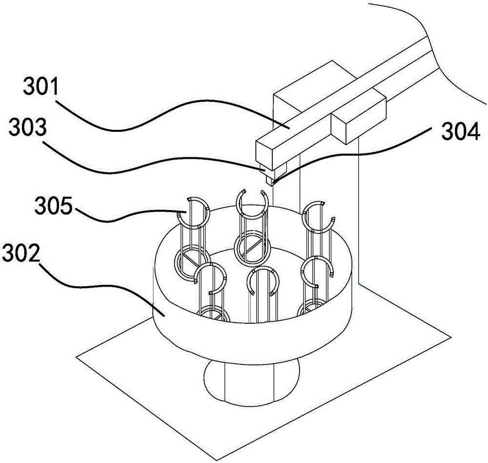
The present invention provides an automatic detection apparatus, and belongs to the technical field of machinery, wherein the problem that the material feeding and the material discharge of the existing work-piece detection equipment adopt the artificial manner so as to provide low efficiency is solved. The automatic detection apparatus comprises a rack and a rotation disk, wherein the rack is provided with a material inlet device, a first detection device, a second detection device, a qualified product receiving device and a defective product receiving device, a plurality of benchmark plates are uniformly distributed on the rotation disk, the material inlet device comprises a guide column, a rotation table and a rotating motor, the guide column is vertically provided with a material taking telescopic gas cylinder, the material taking telescopic gas cylinder is provided with a material inlet suction nozzle, a product placement fixture is placed on the rotation table, the qualified product receiving device comprises a material storage mechanism and a material receiving mechanism arranged on the rack, the defective product receiving device comprises a recovery assembly and a grabbing assembly, and the detected defective product work-piece can be transferred into the recovery assembly with the grabbing assembly. The automatic detection apparatus has advantages of high work efficiency, high detection precision and high automation degree.

Description

technical field [0001] The invention belongs to the technical field of machinery and relates to a detection device, in particular to an automatic detection device for detecting automobile oil seals. Background technique [0002] In the process of leaving the factory, it is necessary for each product to detect whether the surface of the product is flawed and whether the size of the product meets the requirements. In the existing production line, inspection is generally done manually, which is not only time-consuming but also more harmful to the eyes of workers. [0003] Among the existing automatic detection equipment, for example, the Chinese patent "An automatic detection method for photovoltaic module quality" with the publication number CN103022219 discloses a general method for detecting cell cracks, that is, taking pictures with an infrared camera, comparing pictures, and providing software. As a result of the judgment, the patent provides a relatively rough detection ...

Claims


Application Information

Patent Timeline
Patent Type & Authority Patents(China)
IPC IPC(8): B07C5/00B07C5/02B07C5/38
Inventor 徐洪朱兴炜陈晓平徐永锋
Owner ZHEJIANG GREEN NEW MATERIALS
Learn More