A leaf spring hydraulic quenching forming device

A hydraulic and leaf spring technology, applied in the field of leaf spring hydraulic quenching and forming devices, can solve the problems of increased operator workload, high cost of replacing medium, and high operating cost, and achieves a reduction in labor intensity, high production efficiency, and low operating costs. Effect

Inactive Publication Date: 2015-12-09
湖北鄂钢驰久钢板弹簧有限公司
View PDF2 Cites 0 Cited by
  • Summary
  • Abstract
  • Description
  • Claims
  • Application Information

AI Technical Summary

Problems solved by technology

[0003] The existing equipment has a total of 2 conveyor chains, 6 sets of quenching hydraulic systems, and a 50-ton oil tank; 2 transmission conveyor chains, covering a large area of ​​nearly 60 square meters; the cost of primary equipment investment is high; more than 50 tons are required for operation Quenching medium, high operating cost, high cost of replacing the medium; and the operator goes back and forth to 6 sets of quenching fixtures, which increases the workload of the operator

Method used


Image

  • A leaf spring hydraulic quenching forming device
  • A leaf spring hydraulic quenching forming device
  • A leaf spring hydraulic quenching forming device

Examples


Embodiment Construction

[0022] The present invention will be further described below in conjunction with the embodiments shown in the accompanying drawings.

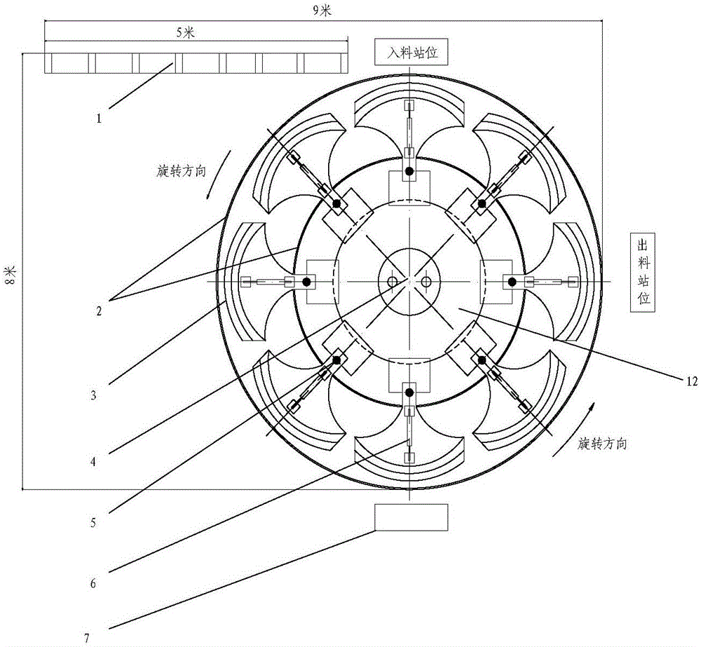
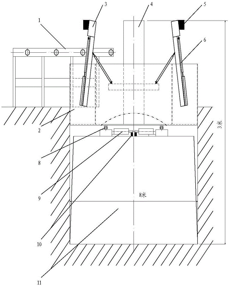
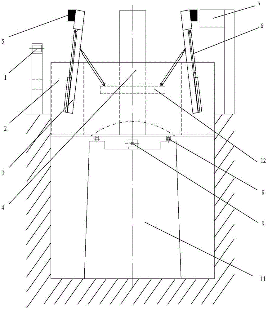
[0023] as attached Figure 1-3 As shown, the present invention includes a support column 11, a disc, an annular oil tank 2, a central valve 4, 8 sets of forming fixtures 3, a fixture cylinder 6, a support roller 8, a driving and braking hydraulic cylinder 9, a plunger pump motor unit, and PLC control system, the forming fixture 3 is provided with a fixture cylinder 6, and the control system includes an induction plate 7 and a proximity switch 5;

[0024] The disc is located in the middle of the annular oil tank 2, the support roller 8 is connected to the disc, the disc and the support roller are installed above the support column 11, the disc is connected to the support roller, and the support column is provided with an annular track corresponding to the support roller; the center The valve 4 and the forming fixture 3 are fixed on the disk, wh...


PUM


Abstract

The invention provides a hydraulic forming and quenching device for plate springs, and the hydraulic forming and quenching device comprises a support pillar, a disc, an annular oil groove, a center valve, a forming fixture, a supporting roller, a driving and braking hydraulic oil cylinder, a plunger pump motor set, and a PLC (programmable logic controller)-based control system, wherein the forming fixture is provided with a fixture oil cylinder, and the control system comprises an induction plate and a proximity switch. The length of a stokehold rotating conveying chain required by the device disclosed by the invention is just 5 meters, and the forming fixture is annularly arranged, so that the hydraulic forming and quenching device for the plate springs disclosed by the invention is small in land-occupied area and small in application amount of a quenching medium, therefore, the hydraulic forming and quenching device for the plate springs is low in cost for putting into operation and high in production efficiency, the positions of operators are fixed, and the implementation of mechanized operation is facilitated.

Description

technical field [0001] The invention belongs to the technical field of leaf spring processing, in particular to a hydraulic quenching and forming device for leaf springs. Background technique [0002] In the heat treatment and forming process of leaf spring, a larger quenching oil tank is often used, about 50 tons of quenching oil. The steel plate to be processed is delivered to six sets of 3-cylinder quenching fixtures through a nearly 60-meter-long transport chain. The operator goes back and forth to the quenching fixture to manually load the material. After forming, the 60-meter-long oil chain plate in the oil tank is used to transport the quenched steel plate. [0003] The existing equipment has a total of 2 conveyor chains, 6 sets of quenching hydraulic systems, and a 50-ton oil tank; 2 transmission conveyor chains, covering a large area of ​​nearly 60 square meters; the cost of primary equipment investment is high; more than 50 tons are required for operation The quen...

Claims


Application Information

Patent Timeline
Patent Type & Authority Patents(China)
IPC IPC(8): C21D1/673C21D9/02
Inventor 戴进涛彭波刘金安周良权周炳超张少清刘春红何木生
Owner 湖北鄂钢驰久钢板弹簧有限公司
Why Eureka
Try Eureka