
A connection structure and connection construction method of monitoring pipe and vacuum membrane in soft foundation treatment

A technology for soft foundation treatment and connection structure, which is applied in basic structure engineering, soil protection, construction, etc. It can solve the problems of cracking and air leakage at the connection, maintenance of the joint that cannot be maintained, maintenance and remediation that cannot be repaired, etc., and achieves good sealing. , stable performance, simple material effect

Active Publication Date: 2015-10-28
CCCC ROAD & BRIDGE SPECIAL ENG
View PDF6 Cites 0 Cited by
  • Summary
  • Abstract
  • Description
  • Claims
  • Application Information

AI Technical Summary

Problems solved by technology

In vacuum preloading, most of them use glue to seal the sealing film and monitoring tube intact, and some people use plastic flange connection, but these methods are difficult to implement in vacuum-surcharge combined preloading construction
Since the detection tube needs to be fixed, the burial depth is greater than the depth of the foundation treatment. During the vacuum preloading construction, the vacuum membrane is settling and moving relative to the monitoring tube, and it is necessary to manually maintain the joint to prevent cracking and air leakage; In the joint preloading construction, the bonded joints cannot be maintained after loading. If the connection between the monitoring tube and the vacuum membrane is handled according to the method of vacuum preloading, the joint will crack and leak with the occurrence of settlement and cannot be maintained. Remediation, resulting in failure of foundation treatment

Method used


Image

  • A connection structure and connection construction method of monitoring pipe and vacuum membrane in soft foundation treatment
  • A connection structure and connection construction method of monitoring pipe and vacuum membrane in soft foundation treatment

Examples


Embodiment 1

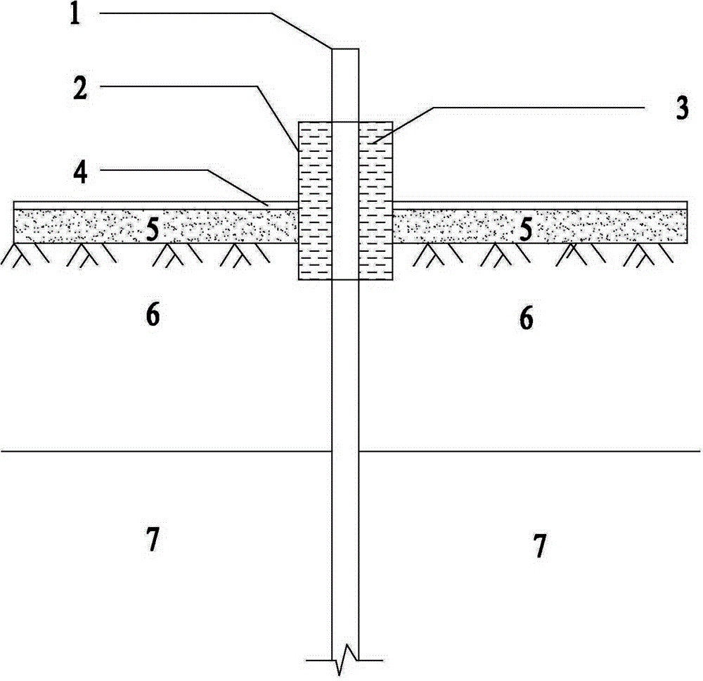
[0028] A method for connecting a monitoring tube and a vacuum membrane in soft ground treatment, comprising the following steps:

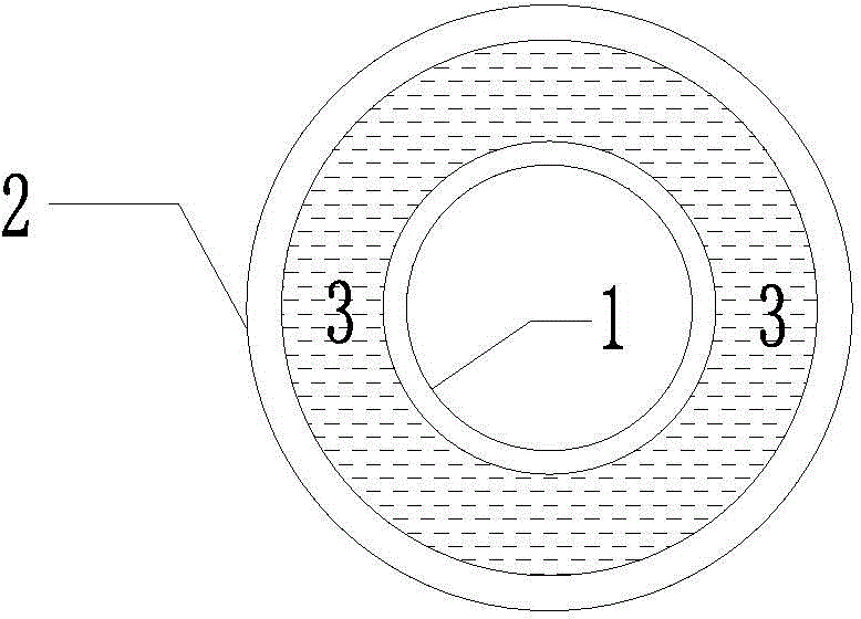
[0029] a. Drill the hole vertically until the base layer, bury the lower end of the monitoring pipe 1 in the base layer 2m, and the upper end of the monitoring pipe 1 is 1m higher than the sand cushion layer 5;

[0030] b. Coaxially embed casing 2 outside the monitoring pipe 1, the diameter of the casing 2 is 5cm larger than the monitoring pipe 1, the lower end of the casing 2 reaches 1m in the foundation treatment layer 6, and the upper end of the casing 2 flush with the upper end of the monitoring tube 1;

[0031] c. the vacuum film 4 is tiled on the sand cushion 5 and the opening of the vacuum film 4 passes through the casing 2, and the vacuum film 4 is bonded with waterproof glue around the casing 2;

[0032] d. Pour the clay slurry 3 into the gap between the casing and the monitoring pipe, the lower liquid level of the clay slurry is in the f...

Embodiment 2

[0036] A method for connecting a monitoring tube and a vacuum membrane in soft ground treatment, comprising the following steps:

[0037] a. Drill the hole vertically until the base layer, bury the lower end of the monitoring pipe 1 in the base layer 1.2m, and the upper end of the monitoring pipe 1 is 1m higher than the sand cushion layer 5;

[0038] b. Coaxially embed casing 2 outside the monitoring pipe 1, the diameter of the casing 2 is 4cm larger than the monitoring pipe 1, the lower end of the casing 2 reaches 4m in the foundation treatment layer 6, and the upper end of the casing 2 0.5m lower than the upper end of the monitoring tube 1;

[0039] c. the vacuum film 4 is tiled on the sand cushion 5 and the opening of the vacuum film 4 passes through the casing 2, and the vacuum film 4 is bonded with waterproof glue around the casing 2;

[0040] d. Pour the clay slurry 3 into the gap between the casing and the monitoring pipe, the lower liquid level of the clay slurry is i...

Embodiment 3

[0044] A method for connecting a monitoring tube and a vacuum membrane in soft ground treatment, comprising the following steps:

[0045] a. Drill the hole vertically until the base layer, bury the lower end of the monitoring pipe 1 in the base layer 1m, and the upper end of the monitoring pipe 1 is 1m higher than the sand cushion layer 5;

[0046] b. Coaxially embed casing 2 outside the monitoring pipe 1, the diameter of the casing 2 is 6cm larger than the monitoring pipe 1, the lower end of the casing 2 reaches 2m in the foundation treatment layer 6, and the upper end of the casing 2 flush with the upper end of the monitoring tube 1;

[0047] c. the vacuum film 4 is tiled on the sand cushion 5 and the opening of the vacuum film 4 passes through the casing 2, and the vacuum film 4 is bonded with waterproof glue around the casing 2;

[0048] d. Pour the clay slurry 3 into the gap between the casing and the monitoring pipe, the lower liquid level of the clay slurry is in the f...


PUM


Abstract

The invention discloses a monitoring pipe and vacuum film connecting structure and a connecting construction method in soft foundation treatment. The connecting construction method includes the following steps: vertically drilling into foundation soil, burying the lower end of a monitoring pipe in the foundation soil, and enabling the upper end of the monitoring to be higher than a sand cushion layer; coaxially burying a sleeve outside the monitoring pipe, enabling the lower end of the sleeve to reach a foundation treatment layer, and enabling the upper end of the sleeve to be flush with or lower than the upper end of the monitoring pipe; laying a vacuum film on the sand cushion layer, enabling an opening of the vacuum film to penetrate the sleeve, and connecting the vacuum film with the four sides of the sleeve in a bonded manner; pouring clay slurry in a gap between the sleeve and the monitoring pipe, and enabling liquid level of the clay slurry to be flush with or higher than the surface of the sand cushion layer; cutting off the sleeve and the monitoring pipe after settlement of the foundation treatment layer is completed, and using a surcharged material to backfill the gap between the sleeve and the monitoring pipe densely. The monitoring pipe and vacuum film connecting structure and the connecting construction method have the advantages of simplicity in material, flexibility in operation and high sealability.

Description

technical field [0001] The invention relates to the technical field of soft soil foundation treatment engineering, in particular to a connection structure between a monitoring pipe fitting and a vacuum membrane and a connection construction method in a vacuum-surcharge combined preloading method. Background technique [0002] Vacuum-surcharge combined preloading method is a soft soil foundation treatment technology developed in recent years. It has the dual effects of vacuum preloading and surcharged preloading, and can effectively solve the settlement and stability problems of soft soil. It has construction technology Simple, large treatment depth, small post-construction settlement, low construction cost and other characteristics, it is widely used in various soft soil foundation treatment projects. [0003] In the construction of vacuum-surcharge combined preloading method, it is necessary to set up monitoring pipe devices such as layered settlement and pore water pressur...

Claims


Application Information

Patent Timeline
Patent Type & Authority Patents(China)
IPC IPC(8): E02D3/10
Inventor 蒋小鹏孟宪鹏乐绍林李少莉吴俊明朱慈祥
Owner CCCC ROAD & BRIDGE SPECIAL ENG
Learn More