Supercharge Your Innovation With Domain-Expert AI Agents!

Vacuum type screw engine

An engine and vacuum technology, applied in the field of vacuum screw engines, can solve the problems of energy consumption and environmental pollution, and achieve the effect of low production cost and simple structure

Inactive Publication Date: 2014-07-16
冯桂华
View PDF3 Cites 0 Cited by
  • Summary
  • Abstract
  • Description
  • Claims
  • Application Information

AI Technical Summary

Problems solved by technology

[0003] The purpose of the present invention is to provide a vacuum screw engine that uses natural air pressure to convert it into mechanical energy to solve the problems of energy consumption and environmental pollution.

Method used


Image

  • Vacuum type screw engine
  • Vacuum type screw engine
  • Vacuum type screw engine

Examples


Embodiment 1

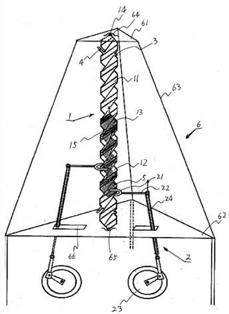
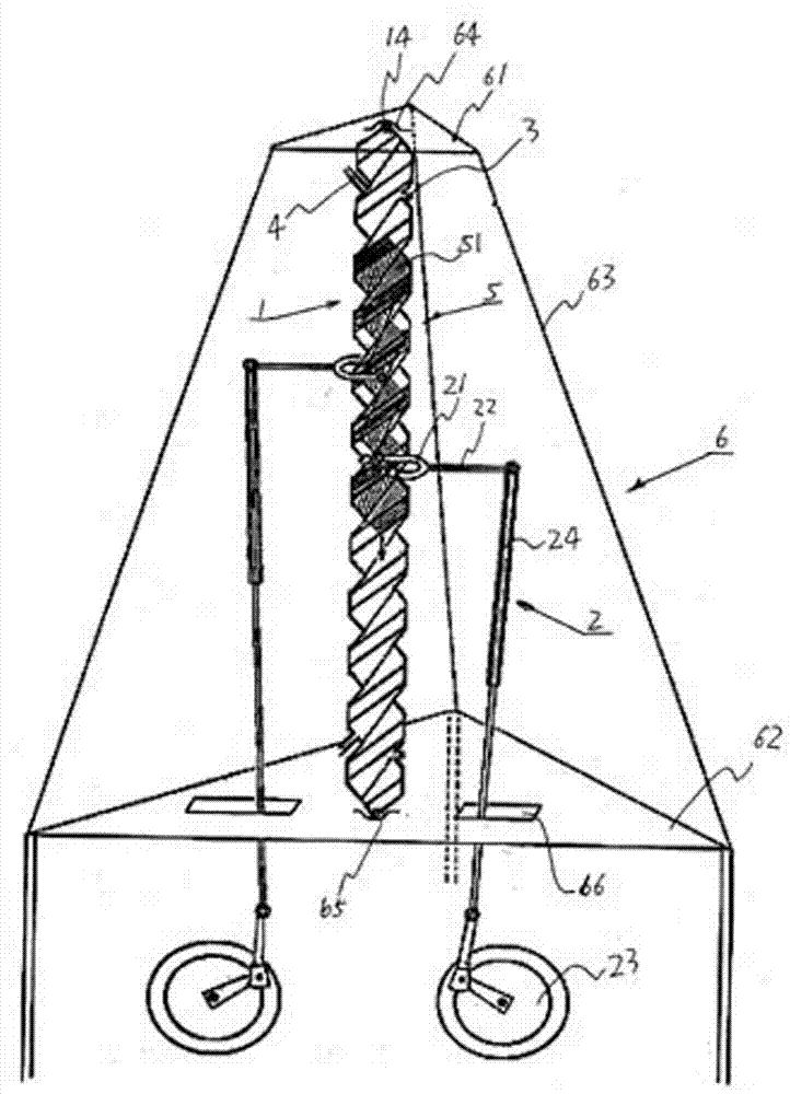
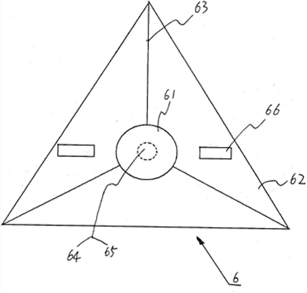
[0023] see Figure 1 to Figure 8 , these six figures provide the appearance structure of the first embodiment of the vacuum screw engine proposed by the present invention. The engine includes a hollow screw 1 , a transmission assembly 2 , an exhaust assembly, a screw driver 5 and a support assembly 6 . The outer surface of the hollow screw 1 is provided with an external thread 11 and the inner surface of the hollow part 12 is provided with an internal thread 13 opposite to the direction of the external thread 11, and balls 14 are respectively installed on the two top ends of the hollow screw 1, and in Both ends of the hollow screw 1 are provided with exhaust components, and a through hole 15 is provided in the middle area of ​​the hollow part 12 . The exhaust assembly is arranged at both ends of the hollow screw 1 and communicates with the hollow part 12 . The exhaust assembly includes air extraction parts 3 and air valves 4 respectively arranged at both ends of the hollow...


PUM


Abstract

The invention relates to a vacuum type screw engine which comprises a hollow screw with two enclosed ends, a support assembly used for limiting the position of the hollow screw and a transmission assembly driven by the hollow screw. A hollow part in the hollow screw is provided with internal threads, a screw drive element which is installed inside the hollow part and is engaged with the internal threads to move up and down in a rotation mode and exhaust components which are arranged at two ends of the hollow screw and are communicated with the hollow part. The central area of the hollow part is provided with a through hole. The screw drive element of the engine is driven by the air in the natural world in a vacuum state to drive the hollow screw to rotate, and the acting force generated is very large. Thus, the engine can generate large driving force under the condition of not consuming energy.

Description

technical field [0001] The invention relates to a vacuum screw motor. Background technique [0002] Existing engines generally include internal combustion engines, external combustion engines, and electric motors, all of which are machines capable of converting other forms of energy into mechanical energy. Although the mechanical power generated by the above-mentioned engines can drive equipment, vehicles and aircraft to move or generate electricity, the existing engines can only be converted into mechanical energy under the condition of energy consumption, and the energy consumed will cause pollution to the surrounding environment , and the production cost of fuel and gas etc. is higher, so, the engine that does not adopt the mode that can be converted into mechanical energy constitutes is a kind of ideal machine. It is generally believed that although nature has a relatively high pressure air pressure, this air pressure cannot drive parts of any shape to move or rotate in...

Claims


Application Information

Patent Timeline
IPC IPC(8): F01C1/107
Inventor 冯桂华
Owner 冯桂华
Features
  • R&D
  • Intellectual Property
  • Life Sciences
  • Materials
  • Tech Scout
  • Unparalleled Data Quality
  • Higher Quality Content
  • 60% Fewer Hallucinations
Learn More