Epicycloid centrifugal pump impeller

A centrifugal pump impeller and epicycloid technology, applied to pumps, pump components, non-variable pumps, etc., can solve problems such as backflow, large loss at the outlet, and low pumping efficiency

Inactive Publication Date: 2014-07-16
CHONGQING UNIV
View PDF9 Cites 7 Cited by
  • Summary
  • Abstract
  • Description
  • Claims
  • Application Information

AI Technical Summary

Problems solved by technology

[0002] Centrifugal pumps work by using the centrifugal force generated by the water generated by the rotation of the impeller. They are used in water supply systems and fire protection in municipal pipe networks, subway projects, water plants, non-negative pressure equipment, chemical plants, power plants, coal mines, sewage treatment stations and other industries. It is widely used in system and HVAC system; before starting the centrifugal pump, the pump casing and the suction pipe must be filled with water, and then the motor is started, so that the pump shaft drives the impeller and the water to rotate at a high speed, and the water is thrown to the impeller under the action of centrifugal force The outer edge flows into the pressure water pipeline of the water pump throu

Method used


Image

  • Epicycloid centrifugal pump impeller
  • Epicycloid centrifugal pump impeller
  • Epicycloid centrifugal pump impeller

Examples


Embodiment Construction

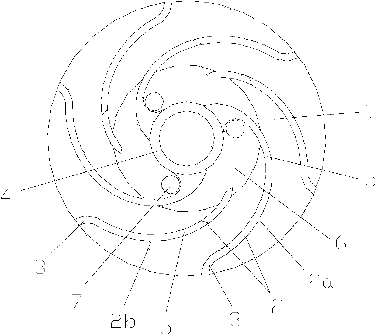
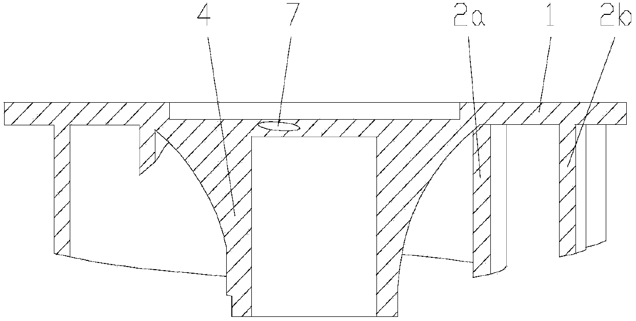
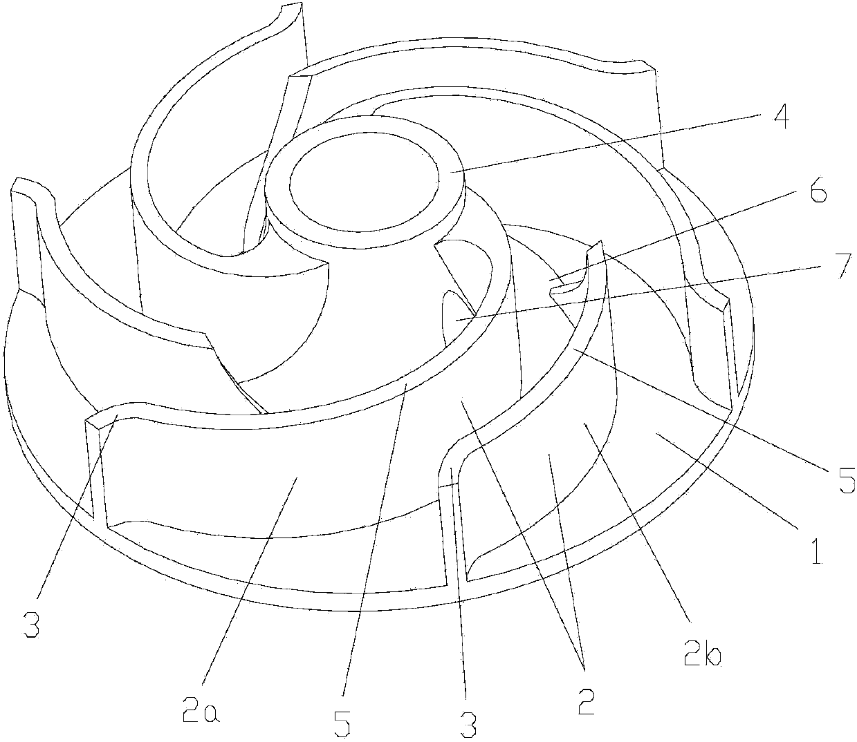
[0029] figure 1 It is a structural schematic diagram of the present invention, figure 2 for figure 1 top view of image 3 For the perspective view of the present invention, Figure 4 is the schematic diagram of the elongated epicycloid, Figure 5 In order to shorten the epicycloid schematic diagram, as shown in the figure: the epicycloid centrifugal pump impeller of the present embodiment includes a wheel disc 1 and a blade 2 fixed on one end surface of the wheel disc 1; the tail section 3 of the blade 2 gradually becomes An epicycloid structure extending radially along the wheel disc 1; the wheel disc 1 is a disc structure with a hub 4 at its center, and the hub 4 extends axially to the side where the blade 2 is located. In this embodiment, the wheel disc 1 and the The blade 2 is combined into a semi-open impeller; the blade 2 is divided into two sections, namely the front section 5 close to the hub 4 and the tail section 3 far away from the hub 4; the front section 5 of...


PUM


Abstract

The invention discloses an epicycloid centrifugal pump impeller. The epicycloid centrifugal pump impeller comprises a wheel disc and blades which are fixedly arranged on one end face of the wheel disc. The tail sections of the blades are gradually changed to be of an epicycloid structure which extends in the radial direction of the wheel disc. According to the epicycloid centrifugal pump impeller, molded lines on the tail sections of the blades are epicycloids close to the fluid motion law, the impeller is designed to be in a half-open type, compared with a common centrifugal pump, loss at an outlet of the impeller can be reduced, the partial reflux phenomenon is reduced, and water pumping efficiency is improved.

Description

technical field [0001] The invention relates to a centrifugal pump impeller, in particular to an epicycloid centrifugal pump impeller. Background technique [0002] Centrifugal pumps work by using the centrifugal force generated by the water generated by the rotation of the impeller. They are used in water supply systems and fire protection in municipal pipe networks, subway projects, water plants, non-negative pressure equipment, chemical plants, power plants, coal mines, sewage treatment stations and other industries. It is widely used in system and HVAC system; before starting the centrifugal pump, the pump casing and the suction pipe must be filled with water, and then the motor is started, so that the pump shaft drives the impeller and the water to rotate at a high speed, and the water is thrown to the impeller under the action of centrifugal force The outer edge flows into the pressure water pipeline of the water pump through the flow channel of the volute pump casing....

Claims


Application Information

Patent Timeline
IPC IPC(8): F04D29/22
Inventor 唐倩冯琪翔严迪张元勋肖雄刘宗敏
Owner CHONGQING UNIV
Why Eureka
Try Eureka