Restricted-type expansion joint for flue gas turbine inlet high-temperature flue

A technology of high-temperature flue and steam turbine, which is applied to expansion compensation devices for pipelines, mechanical equipment, engine components, etc., and can solve problems such as weld cracking, medium corrosion, and high-frequency vibration of the draft tube, and avoid adverse effects Effect

Inactive Publication Date: 2014-07-16
LUOYANG SUNRUI SPECIAL EQUIP
View PDF8 Cites 8 Cited by
  • Summary
  • Abstract
  • Description
  • Claims
  • Application Information

AI Technical Summary

Problems solved by technology

The role of the expansion joint to set the guide tube is to protect the bellows from the impact of the high-velocity medium, see Figure 1a and Figure 1b , at present, the guide tube of the expansion joint of the inlet pipeline of the gas turbine is a cantilever beam structure, that is, one end of the guide tube is a fixed end and is welded in the inlet pipe, and the other end is a cantilever end and extends into the outlet pipe. The flow end surface at the inlet of the tube suddenly becomes smaller, and the increase of the medium flow rate will cause high-frequency vibration. In addition, the corrosion of the medium in the pipeline will easily cause the weld end of the guide tube to crack, which will cause the guide tube to fall off and lose the protection of the bellows In addition, the detached guide tube is taken away by the medium, and the fragments of the guide tube enter the smoke turbine, which will damage the moving blades of the smoke turbine and cause serious consequences

Method used


Image

  • Restricted-type expansion joint for flue gas turbine inlet high-temperature flue
  • Restricted-type expansion joint for flue gas turbine inlet high-temperature flue
  • Restricted-type expansion joint for flue gas turbine inlet high-temperature flue

Examples


Embodiment Construction

[0016] The present invention is described in conjunction with accompanying drawing and specific embodiment:

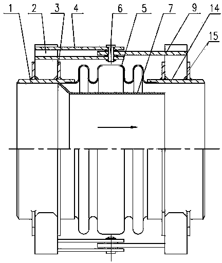
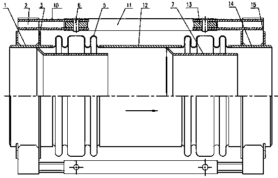
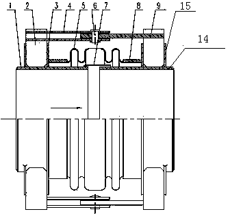
[0017] Such as figure 2 As shown, a constrained expansion joint used for a high-temperature flue at the inlet of a smoke turbine, the constrained expansion joint includes an inlet end pipe 1, an outlet end pipe 14, a bellows 5, a guide tube 7 and a restraint Bellows pressure thrust hinge mechanism; there is a gap between the inlet pipe 1 and the outlet pipe 14, and a bellows is provided on the outside of the inlet pipe 1 and the outlet pipe 14 to connect them as a whole 5. The two ends of the corrugated pipe 5 are respectively connected to the inlet pipe 1 and the outlet pipe 14 through the bellows adapter 8 and the ring plate 3; 7, and the guide tube 7 is located inside the bellows 5; one end of the guide tube 7 is welded on the outer wall surface of the inlet pipe 1 near the end of the outlet pipe, and the other end of the guide tube 7 is located on the outlet pipe...


PUM


Abstract

The invention belongs to the technical field of petrochemical expansion joint compensation, and provides a restricted-type expansion joint for a flue gas turbine inlet high-temperature flue. The restricted-type expansion joint for the flue gas turbine inlet high-temperature flue comprises an inlet end pipe (1), an outlet end pipe (14), a corrugated pipe (5), a flow guiding cylinder (7) and a hinge mechanism. A gap is formed between the inlet end pipe (1) and the outlet end pipe (14). The corrugated pipe (5) and the flow guiding cylinder (7) are arranged on the outer side of the inlet end pipe (1) and the outer side of the outlet end pipe (14), or a middle pipe (12) is arranged between the inlet end pipe (1) and the outlet end pipe (14), a gap is formed between the middle pipe (12) and the inlet end pipe (1), a gap is formed between the middle pipe (12) and the outlet end pipe (14), and the corrugated pipe (5) and the flow guiding cylinder (7) are arranged on the outer side of the inlet end pipe (1), the outer side of the middle pipe (12) and the outer side of the outlet end pipe (14). The restricted-type expansion joint solves the problem of disengagement of the flow guiding cylinder.

Description

technical field [0001] The invention belongs to the technical field of petrochemical expansion joint compensation, and in particular relates to a constrained expansion joint used for a high-temperature flue at the inlet of a smoke-steam turbine. Background technique [0002] In the refining process of petroleum, the regenerated flue gas of the catalytic cracking unit contains a large amount of recoverable energy, accounting for about 26% of the energy consumption of the whole unit. The energy recovery system introduces the flue gas produced by catalytic cracking into the flue gas turbine, recovers its pressure energy to drive the main fan to do work, or drives the generator to generate power, and makes full use of the potential energy and heat energy in the flue gas to generate power to recover the energy of the regenerated flue gas to achieve Energy saving purpose. The temperature of the regeneration flue gas pipeline is 670-720°C, the flue gas flow rate is high, and the p...

Claims


Application Information

Patent Timeline
Patent Type & Authority Applications(China)
IPC IPC(8): F16L51/03F01D25/00
CPCF16L51/03F01D25/00
Inventor 张爱琴王春会王宁
Owner LUOYANG SUNRUI SPECIAL EQUIP
Why Eureka
Try Eureka