Optical fiber vibrating sensor and power transmission line aeolian vibration monitoring system applying the same

A fiber optic vibration and sensor technology, applied in instruments, measuring devices, and using wave/particle radiation, etc., can solve the problems that vibration sensors need on-site power supply, cannot transmit on-site information in real time, and vibration measurement results cannot be transmitted, etc., so as to facilitate long-term monitoring , Improve reliability and stability, fast effect

Active Publication Date: 2014-07-16
STATE GRID CORP OF CHINA +1
View PDF6 Cites 19 Cited by
  • Summary
  • Abstract
  • Description
  • Claims
  • Application Information

AI Technical Summary

Problems solved by technology

[0007] The above existing sensor measurement results need to be transmitted to the monitoring center through wireless means. Due to the unstable wireless communication signal, the vibration measurement results cannot be transmitted.
[0008] Aiming at the problems that the vibration sensors existing in the above-mentioned existing overhead transmission lines require on-site power supply, are easily affected by complex electromagnetic environments, have poor measurement accuracy and sensitivity, large volume, poor system stability, and cannot transmit on-site information in real time, the application of the present invention is proposed

Method used


Image

  • Optical fiber vibrating sensor and power transmission line aeolian vibration monitoring system applying the same
  • Optical fiber vibrating sensor and power transmission line aeolian vibration monitoring system applying the same

Examples


Embodiment 1

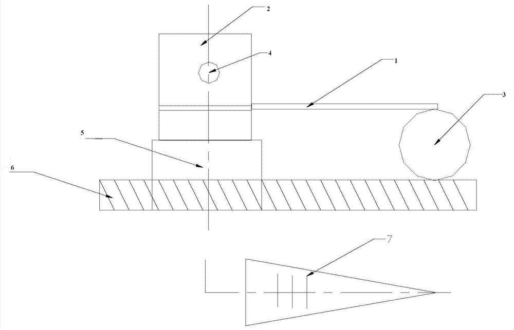
[0030] Such as Figure 1-2 As shown, the optical fiber vibration sensor described in the invention of this example includes equal-intensity beams 1 and fixed bodies 2 connected in sequence, equal-intensity beams 1 and contact bodies 3 arranged on the wires; the fixed body 2 is arranged on the The fixture 5 on the wire 6 is connected to the wire 6, and a fiber Bragg grating 7 is symmetrically pasted on the upper and lower surfaces of the equal-intensity beam 1 perpendicular to the central axis.

[0031] The fixed body 2 is provided with a fiber holder 4, and the fiber end of the fiber Bragg grating 7 passes through the fiber holder 4 and the fiber connector in sequence.

[0032] The equal-strength beam 1 is a cantilever-type elastic body isosceles triangular plate, and its material is preferably beryllium bronze. This material has the advantages of large yield strength, large elastic deformation range, small elastic hysteresis, wear resistance, low temperature resistance, and c...


PUM


Abstract

The invention relates to an optical fiber vibrating sensor and a power transmission line aeolian vibration monitoring system applying the same. The optical fiber vibrating sensor comprises a fixed body, a constant-strength beam and a contact body arranged on a lead wire, wherein the fixed body, the constant-strength beam and the contact body are connected in sequence. The fixed body is connected with the lead wire through a clamp arranged on the lead wire, and the upper and lower surfaces perpendicular to the axis of the constant-strength beam are symmetrically provided with fiber bragg gratings. The sensor is installed by adopting an upright method of hull section construction, and an installing point is a fatigue dangerous point of a ground conductive wire. The monitoring system comprises the optical fiber vibrating sensor, an optical fiber composite overhead ground wire, a wave-length adjusting device and a host machine which are connected in sequence. The sensor and the monitoring system have the advantages of being high in measuring accuracy, high in speed, good in frequency response, stable in long-term performance and the like, the problem that the prior art susceptible to influence of complicated electromagnetic environment, measuring accuracy, poor flexible, large size and poor system stability, cannot achieve field information transfer in real time and the like is solved, and the stability and reliability of the system are improved.

Description

Technical field: [0001] The invention relates to the technical field of on-line monitoring, and more specifically relates to an optical fiber vibration sensor and a power transmission line breeze vibration monitoring system using the sensor. Background technique: [0002] The breeze vibration of transmission line conductor is due to the excitation of wind, which causes the conductor to resonate in the vertical plane, forming a regular wave reciprocating motion up and down. The range of wind speed where vibration occurs is generally 0.5-10m / s, the vibration frequency is generally 3-150Hz, the maximum double amplitude is generally not greater than 1-2 times the diameter of the wire, generally several hours, sometimes up to several days, high-frequency slight amplitude Breeze vibrations are the most frequent, causing different degrees of dynamic bending stress on the conductors, which can easily cause conductor fatigue and broken strands, fatigue damage or wear of fittings, spa...

Claims


Application Information

Patent Timeline
Patent Type & Authority Applications(China)
IPC IPC(8): G01H9/00
Inventor 杨吉
Owner STATE GRID CORP OF CHINA
Why Eureka
Try Eureka