
Multi-beam antenna based on transformation optics

A multi-beam antenna and transformation optics technology, applied to antennas, devices that enable antennas to work in different bands at the same time, electrical components, etc., can solve the problems that require a large dielectric constant medium, rarely process antennas, and are difficult to construct.

Inactive Publication Date: 2014-07-16
HARBIN INST OF TECH
View PDF5 Cites 5 Cited by
  • Summary
  • Abstract
  • Description
  • Claims
  • Application Information

AI Technical Summary

Problems solved by technology

And the proposed gradient refraction lens method obtains the anisotropic and non-uniform electromagnetic parameters of the lens, which is actually difficult to construct
Huang Lujun of the Chinese Academy of Sciences proposed a block triangular transformation method to obtain a uniform medium, but using the effective medium theory to construct a conventional medium still requires a medium with a large dielectric constant, and the anisotropy also makes it difficult for conventional media to meet the requirements
The vast majority of research exists in the theoretical research stage, and few have processed actual antennas

Method used

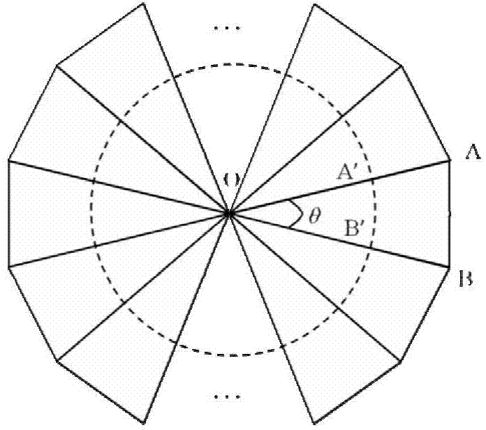
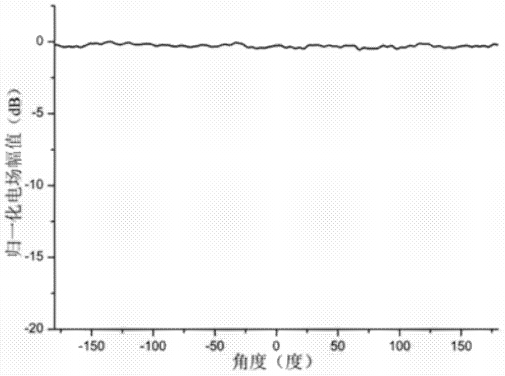
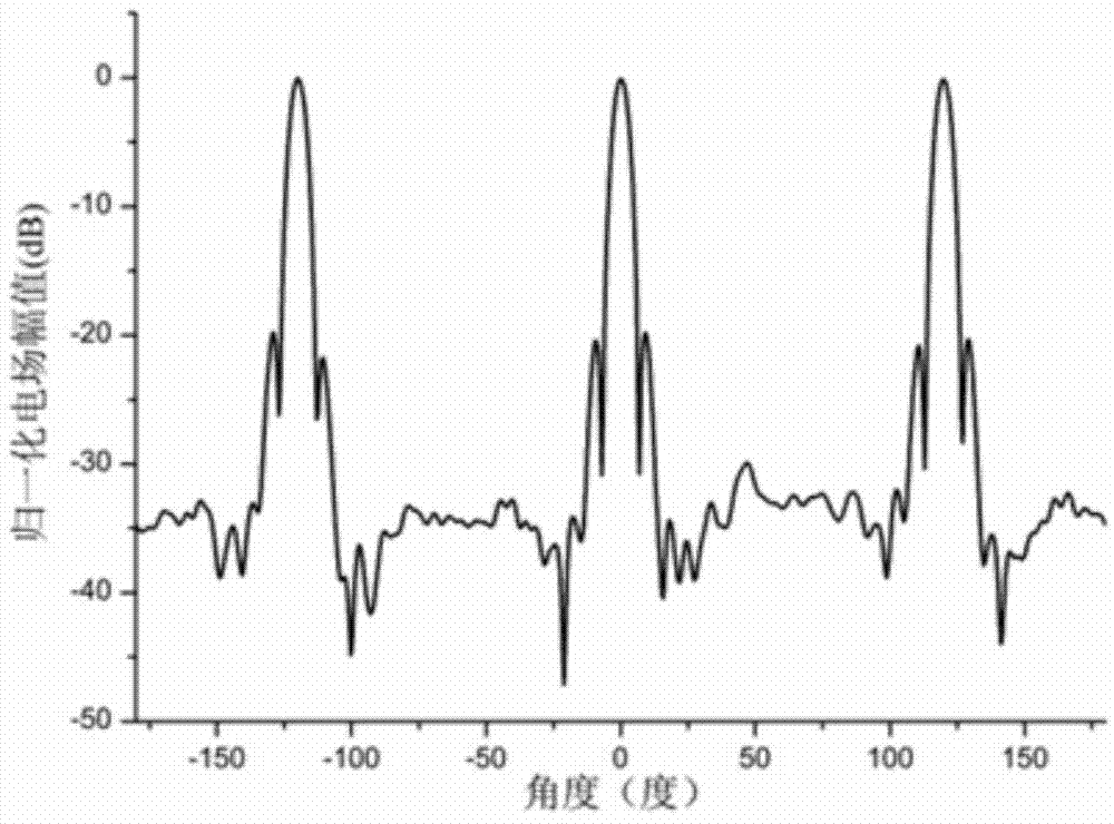

Image

  • Multi-beam antenna based on transformation optics
  • Multi-beam antenna based on transformation optics
  • Multi-beam antenna based on transformation optics

Examples


specific Embodiment approach 1

[0042] Specific implementation mode 1. Combination figure 1 Illustrate this specific embodiment, based on the multi-beam antenna of transformation optics, it comprises dipole antenna 1; It also comprises four lenses 2, two fixed plates 4, four fixed posts 3 and 4N metal strips 5; N is an integer greater than or equal to and less than or equal to 12;

[0043] Each fixed plate 4 is a rectangular frame structure, wherein a rectangular slot is opened in the middle of each frame, and the upper and lower sides of the two fixed plates 4 are arranged oppositely; the two fixed plates 4 are fixed by four fixed columns 3 As a whole; one end of the four fixed columns 3 is located at the four corners of a fixed plate 4; the other end of the four fixed columns 3 is located at the four corners of another fixed plate 4; two adjacent A rectangular lens installation window is formed between the fixed columns 3; the four lenses 2 are respectively embedded and fixed on the four lens installation...

specific Embodiment approach 2

[0045] Embodiment 2. The difference between this embodiment and the multi-beam antenna based on transformation optics described in Embodiment 1 is that it also includes a coaxial cable, wherein a lens 2 has a through hole; the dipole One end of the antenna 1 is connected to one end of the coaxial cable through the through hole.

specific Embodiment approach 3

[0046] Embodiment 3. The difference between this embodiment and the multi-beam antenna based on transformation optics described in Embodiment 2 is that it also includes an insulating and fixing crossbar, and the two ends of the insulating and fixing crossbar are respectively fixed on two On the opposite lens 2, the dipole antenna 1 is fixed on the insulating and fixing cross bar.


PUM

PropertyMeasurementUnit
Thicknessaaaaaaaaaa
Center frequencyaaaaaaaaaa

Abstract

The invention relates to an antenna, in particular to a multi-beam antenna based on transformation optics. The multi-beam antenna is light in structure, easy to structure and small in size, and any N beams are generally suitable for the multi-beam antenna. Taking a four-beam antenna design as an example, each fixing plate is of a rectangular frame structure, a rectangular insertion groove is formed in the middle of each frame, and the two fixing plates are oppositely arranged. The two fixing plates are fixed into a whole through four fixing pillars. One ends of the four fixing pillars are located at the four corners of one fixing plate. The other ends of the four fixing pillars are located at the four corners of the other fixing plate. A rectangular lens installation window is formed between every two adjacent fixing pillars. Four lenses are fixedly embedded into the four lens installation windows respectively. N metal band strips are etched in each lens. A dipole antenna is located in the center of the area formed by the four lenses in a defined mode. The multi-beam antenna is suitable for occasions where multi-beam antennas are applied.

Description

technical field [0001] The invention relates to an antenna. Background technique [0002] There are three commonly used design methods for multi-beam antennas regulated by artificial electromagnetic energy. The first method uses transformation optics to map the intermediate field that approximates a plane wave to the edge area, making the entire field more similar to a plane wave, thereby improving the antenna gain. Transformation optics was first introduced into the field of artificially controlled electromagnetics by Pendry and Leonhardt in 2006. A lot of theoretical research and applications have been produced, such as stealth, perfect lens. In terms of lens research, it is possible to realize multi-beam antennas by filling the transformation medium area around omnidirectional antennas, such as monopole or dipole antennas. But transforming the optical lens will cause the permittivity and permeability dyadic vector to be very complicated, and it is not easy to realize. ...

Claims


Application Information

Patent Timeline
IPC IPC(8): H01Q5/00H01Q19/06
Inventor 张狂傅佳辉沃得良
Owner HARBIN INST OF TECH
Learn More