Sound wave transmitting device

A technology of conduction device and sound wave, which is applied in the direction of frequency/direction characteristic device, etc., which can solve the problems of loss of high-frequency sound pressure, increase of waveguide reflection, etc., and achieve effective phase adjustment, reduction of reflection, and wide coverage.

Inactive Publication Date: 2014-07-16
赵春宁
View PDF4 Cites 8 Cited by
  • Summary
  • Abstract
  • Description
  • Claims
  • Application Information

AI Technical Summary

Problems solved by technology

The above-mentioned consensus is to increase the extension of the front plus horn in the horizontal direction enough, so that there is enough coverage in the horizontal direction. In this way, the waveguide presents two kinds of horizontal and vertical waves that are far apart during the entire internal sound transmission process. In order to reduce the width of the exit path and create too much internal negative curvature, but the above approach will greatly increase the reflection inside the waveguide, the result is a great loss of high-frequency sound pressure, which is different from the use of multiple speakers The opposite result of increasing the high-frequency sound pressure

Method used


Image

  • Sound wave transmitting device
  • Sound wave transmitting device
  • Sound wave transmitting device

Examples


Embodiment Construction

[0025] The present invention will be described in further detail below in conjunction with the accompanying drawings.

[0026] Figure 1 to Figure 7 Schematically shows the structure of an acoustic wave conducting device according to an embodiment of the present invention.

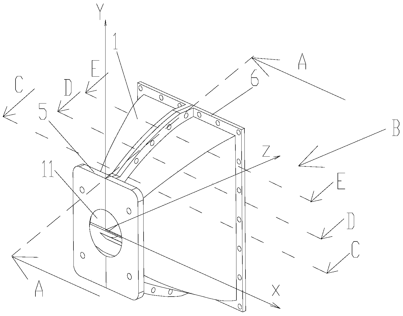
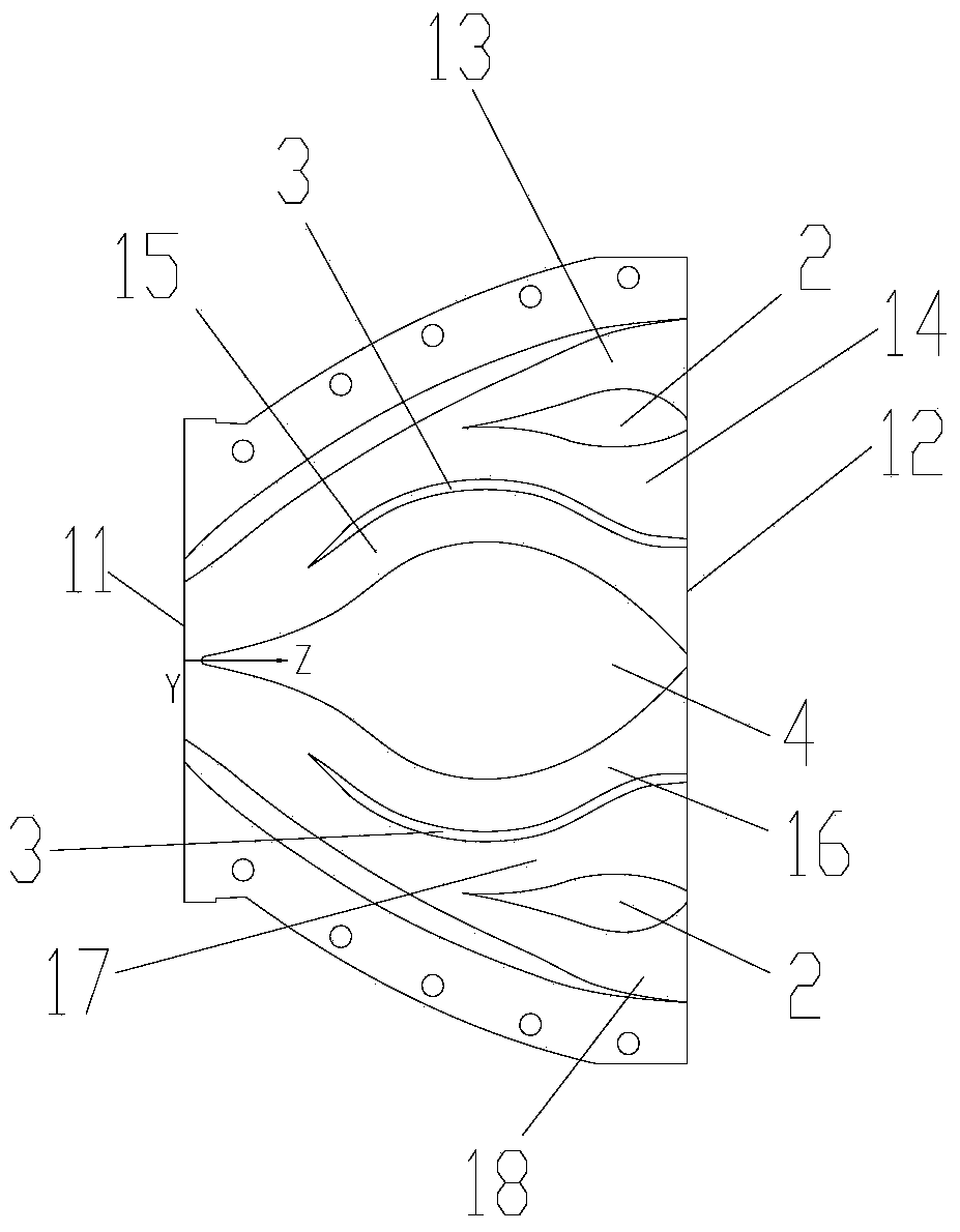
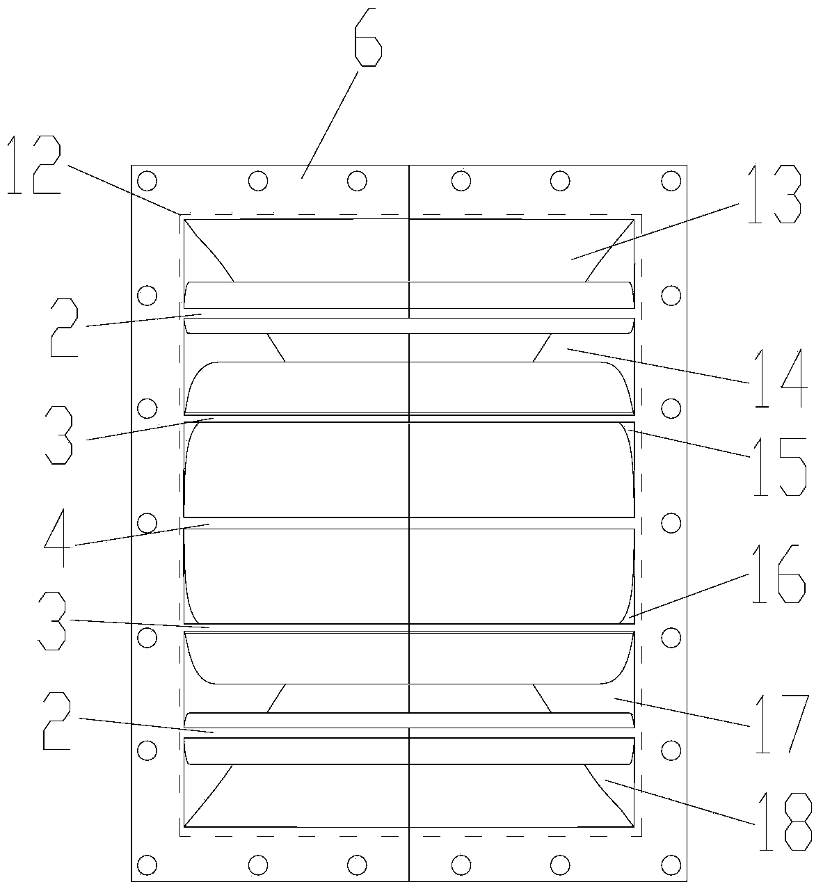
[0027] like Figure 1 to Figure 7 As shown, the sound wave conducting device includes a main body 1 . In addition, the sound wave conducting device may further include a first split body 2 , a second split body 3 , a fourth split body 4 , a first flange side 5 and a second flange side 6 .

[0028] like figure 1 and figure 2 As shown, one side of the main body 1 is formed with a sound wave input port 11, and the other side is formed with a sound wave output port 12, and the main body 1 is along the centerline direction from the sound wave input port 11 to the sound wave output port 12 (such as figure 1 and figure 2 The shown Z direction) presents a three-dimensional diffusion trend, which reduces th...


PUM


Abstract

The invention discloses a sound wave transmitting device. The sound wave transmitting device comprises a main body, one side of the main body is provided with a sound wave input port, the other side of the main body is provided with a sound wave output port, the main body is in a three-dimensional diffusion trend in the direction of a center line from the sound wave input port to the sound wave output port. The area of the sound wave output port is larger than that of the sound wave input port. A plurality of channels are arranged in the main body, the inlet of each channel starts from the sound wave input port, the outlets of all channels are independent from one another and stop in the sound wave output port, the path distances of channels are equal, and the cross sections of all the channels at the same positions are equal. Sound waves entering the main body pass through the channels with the equal path distances and the same cross sections at the same position, the phase positions of the sound waves transmitted out of the outlets of the channels are basically the same, the sound waves have good same-frequency overlaying performance after passing through the sound wave transmitting device, the reflection of the sound waves in the main body can be reduced due to the fact that the main body is in the three-dimensional diffusion trend in the direction of the center line from the sound wave input port to the sound wave output port, the frequency response characteristics of the sound waves can be improved, and standing wave distortion can be reduced.

Description

technical field [0001] The invention relates to a device for improving sound wave propagation, in particular to a sound wave conducting device. Background technique [0002] When a single loudspeaker radiates into the air through a single horn, the sound wave will generate reflection and phase interference inside the horn, which will degrade the high frequency and make the frequency response uneven. When multiple loudspeakers form a vertical array for conduction, the mutual The phase interference will produce frequency cancellation and affect the desired superposition of the same frequency response. [0003] Many foreign companies have invented acoustic waveguides to solve the above problems, mainly to solve the phase interference, but the international consensus is that the length direction of the waveguide is divided according to half of the wavelength, but the width direction needs to be as small as possible, generally close to The high-frequency half-wavelength is usual...

Claims


Application Information

Patent Timeline
Patent Type & Authority Applications(China)
IPC IPC(8): H04R1/20
Inventor 赵春宁
Owner 赵春宁
Why Eureka
Try Eureka