Compact undulator system and methods

A undulator and fastening technology, applied in the field of insertion devices, can solve the problems of expensive undulators, and achieve the effects of weight reduction, easy transportation, and promotion of facility renewal

Active Publication Date: 2014-07-16
CORNELL UNIVERSITY
View PDF2 Cites 7 Cited by
  • Summary
  • Abstract
  • Description
  • Claims
  • Application Information

AI Technical Summary

Problems solved by technology

Also, undulators are usually very expensive

Method used


Image

  • Compact undulator system and methods
  • Compact undulator system and methods
  • Compact undulator system and methods

Examples


Embodiment Construction

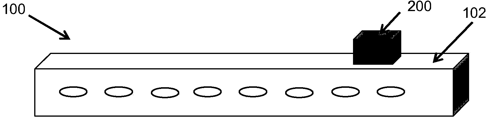
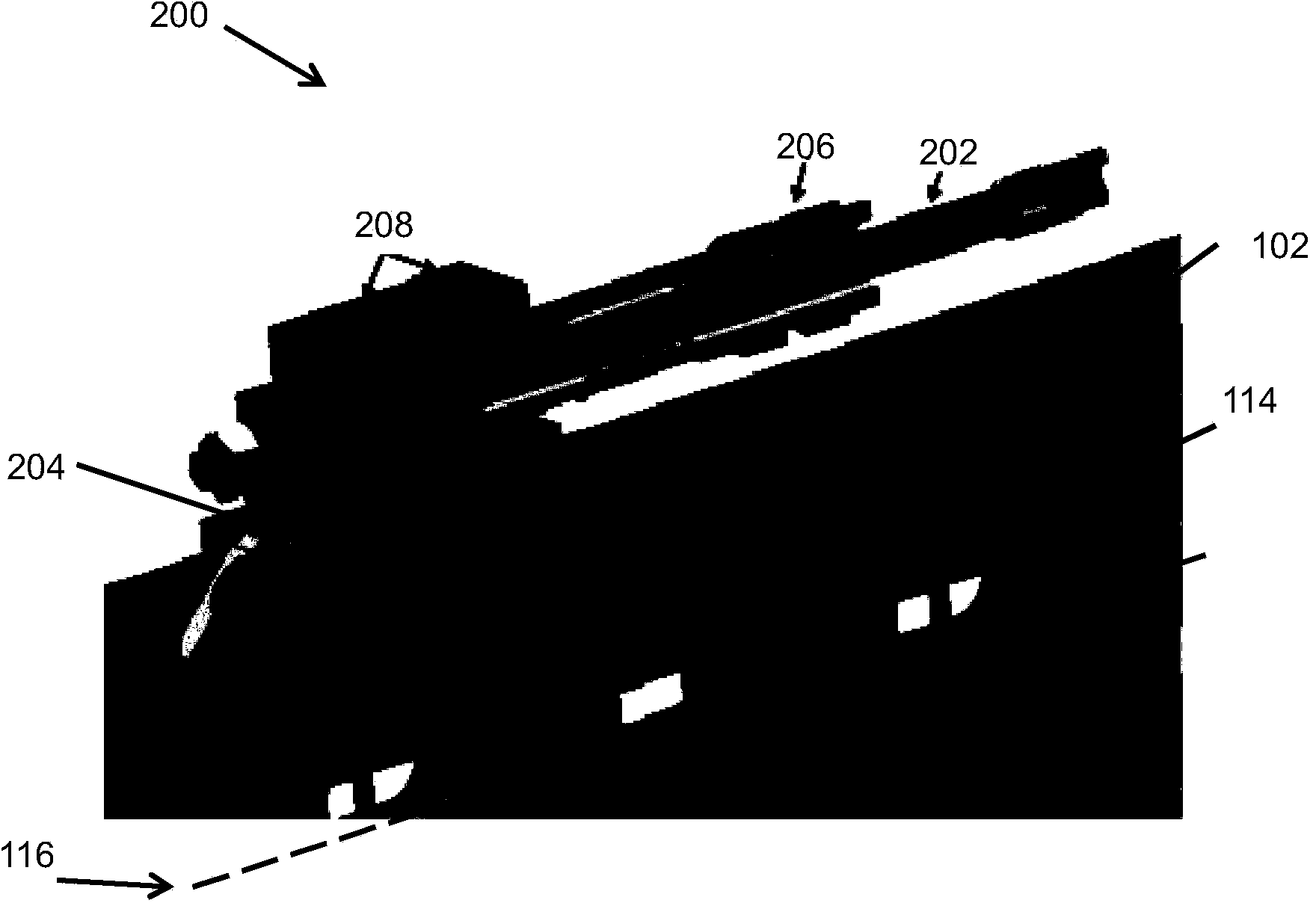
[0031] figure 1 and figure 2 An undulator 100 according to an embodiment of the invention is shown. like figure 1 As shown, the undulator 100 includes a rectangular box-shaped frame 102 and a drive mechanism 200 . In the embodiment of the present invention, the rectangular box-shaped frame 102 can be made of aluminum material, specifically, four pieces of one-meter-long, 24mm and 30mm thick aluminum plates (6061-T6 alloy). The total weight of the frame may be around 35 kg. A unique feature of the rectangular box-like frame 102 is that the force loop is housed within a small strong structure. In other words, the rectangular box frame 102 is much stronger than the traditionally used C-shaped frame structure. Where large vertical forces typically cause the magnet beams to wobble in conventional solutions, the rectangular box-like frame 102 and lateral symmetry effectively eliminate this deformation.

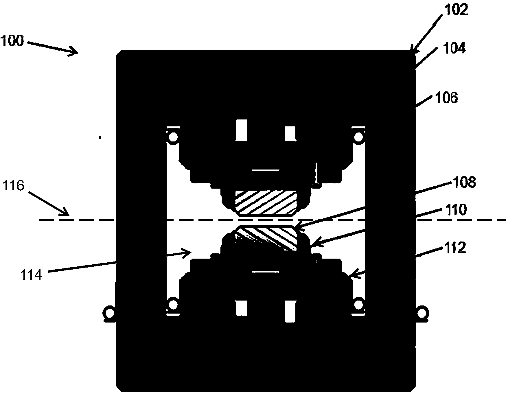
[0032] like figure 2 As shown in the cross-sectional view of the undul...


PUM


Abstract

An undulator with a compact construction is provided that reduces weight, complexity and cost. The compact undulator system and methods provides mechanical integrity without compromising magnetic field quality.

Description

[0001] priority [0002] This application claims the benefit of US Provisional Patent Application No. 61 / 521,606, filed August 9, 2011. [0003] government rights [0004] This invention was made with government support DMR-0936384 and DMR-0807731 awarded by the National Science Foundation. The US Government has certain rights in this invention. technical field [0005] The present invention relates generally to insertion devices and, more particularly, to undulator systems and methods employing compact structures that are mechanically integrated and do not compromise magnetic field quality, thereby reducing weight, complexity, and cost. Background technique [0006] Undulators are magnetic component insertion devices that are used in synchrotron radiation sources such as free electron lasers (FEL) and storage rings. Undulators are also used in medicine and industry for the use of X-rays or photon beams with longer wavelengths. [0007] In particular, an undulator includ...

Claims


Application Information

Patent Timeline
Patent Type & Authority Applications(China)
IPC IPC(8): H01S3/09
CPCH01S3/0903H05G2/00H05H2007/041B23K35/3601H05H7/04H01F7/0284B23K1/0008B23K1/203H01F41/0253H01F1/057
Inventor A·特姆奈科
Owner CORNELL UNIVERSITY
Why Eureka
Try Eureka