Automatic cutting machine

A cutting machine and automatic technology, applied in the field of mechanical processing, can solve problems such as time-consuming, inefficient, unsafe, etc., and achieve the effect of easy and understandable operation

Active Publication Date: 2014-07-23
东莞市塘厦肇颖机械五金厂
View PDF5 Cites 18 Cited by
  • Summary
  • Abstract
  • Description
  • Claims
  • Application Information

AI Technical Summary

Problems solved by technology

[0002] The current manufacturing industry pursues a high-efficiency and safe production mode, and thus creates the interests of the enterprise. However, in the existing manufacturing industry, the cutting operation is to adopt Manual control of operations not only takes time and increases labor costs, but is also inefficient and unsafe, and a little carelessness during operation will cause the operator to be injured
[0003] Taking sheet leather and fabric as an example, the traditional manual cutting method must first manually measure the required length, and manually place the edge of the material to align with the knife edge , and then cutting with a cutter is not only time-consuming and inefficient, but also the length of cutting may be different due to human factors, resulting in lower product yield, different production quantities of sheet materials, and waste of manpower and unsafe

Method used


Image

  • Automatic cutting machine
  • Automatic cutting machine

Examples


Embodiment 1

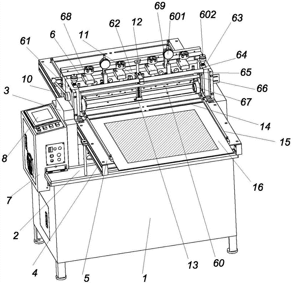
[0021] Embodiment one: like figure 1 As shown, an automatic cutting machine includes a working machine platform 1. A working table surface 2 is provided on the upper end of the working machine platform 1, and two corresponding supports 3 are arranged on the working table surface 2. Between the two supporting seats 3 A workpiece conveying platform support 4 is arranged between them, and two corresponding workpiece conveying platforms 5 are arranged on the workpiece conveying platform support 4, a cutting device 6 is arranged between the two workpiece conveying platforms 5, and a cutting device 6 is arranged on one side of the working machine platform 1. There is an electrical distribution box 7 , and one end of the working surface 2 is provided with a touch-sensitive operation panel 8 , and the touch-sensitive operation panel 8 and the cutting device 6 are electrically connected to the electrical distribution box 7 respectively. The page of the touch-sensitive operation panel...

Embodiment 2

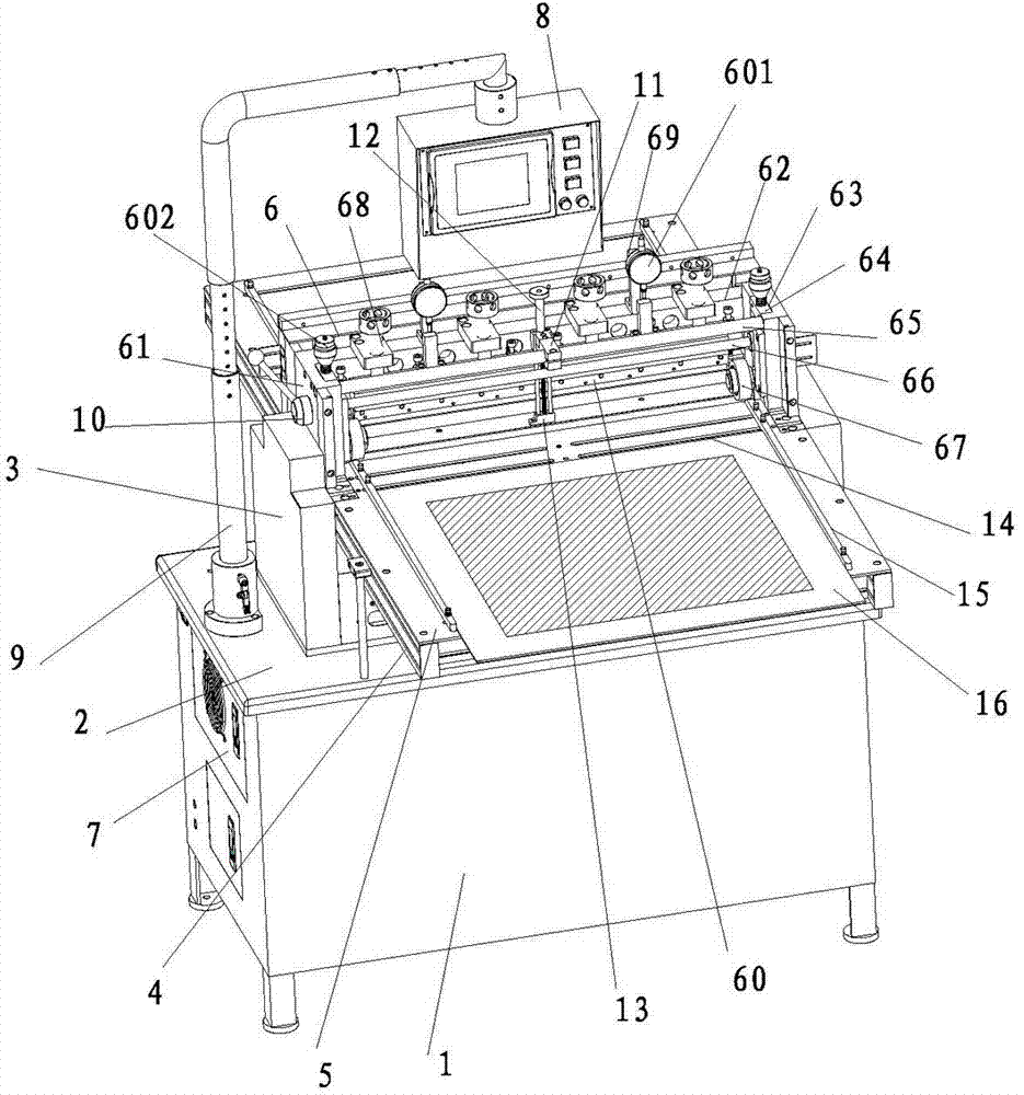
[0030] Embodiment two: like figure 2 As shown, an automatic cutting machine includes a working machine platform 1. A working table surface 2 is provided on the upper end of the working machine platform 1, and two corresponding supports 3 are arranged on the working table surface 2. Between the two supporting seats 3 A workpiece conveying platform support 4 is provided between them, and two corresponding workpiece conveying platforms 5 are arranged on the workpiece conveying platform support 4, a cutting device 6 is arranged between the two workpiece conveying platforms 5, and a cutting device 6 is arranged on one side of the working machine platform 1. There is an electrical distribution box 7, one end of the work surface 2 is provided with a touch-sensitive operation panel 8, the touch-sensitive operation panel 8 and the cutting device 6 are respectively electrically connected to the electrical distribution box 7, and the touch-sensitive operation panel 8 passes through a L...


PUM


Abstract

The invention discloses an automatic cutting machine which comprises a work machine table. The upper end of the work machine table is provided with a work table top. The work table top is provided with two supports corresponding to each other. A work-piece conveying table bracket is arranged between the two supports and provided with two corresponding work-piece conveying tables. A cutting device is arranged between the two work-piece conveying tables. One side of the work machine table is provided with an electrical appliance power distribution cabinet. One end of the work table top is provided with a touch type operation panel. Flaky materials are placed on an acrylic plate, a start key is pressed, and feeding idler wheels can advance in a running-down mode; when a photoelectric sensor senses coming of the materials, the edges can be automatically cut and trimmed neatly according to the length set by the photoelectric cardinal number, fixed length cutting is carried out and the cutting number is controlled according to the cut length set by a numerical control device; after the number of cutting is finished, the feeding idler wheels enable the acrylic plate to retreat to the original start position according to the length set by the reversing length.

Description

technical field [0001] The invention relates to the field of mechanical processing, in particular to an automatic cutting machine for shielding materials, adhesive materials, insulating materials, conductive materials and foam materials in various sheet leather, cloth, paper and electronic industries. Background technique [0002] The current manufacturing industry pursues a high-efficiency and safe production mode, and thus creates the interests of the enterprise. However, in the existing manufacturing industry, the cutting operation is manually controlled, which is not only time-consuming but also increases labor costs. Efficiency is not safe again, a little carelessness during operation will cause operator to be injured. [0003] Taking sheet leather and fabric as an example, the traditional manual cutting method requires first manually measuring the required length, manually placing the edge of the material to align with the knife edge, and then cutting with a cu...

Claims


Application Information

Patent Timeline
Patent Type & Authority Applications(China)
IPC IPC(8): B26D1/01B26D7/28B26D7/26C14B5/00C14B17/00D06H7/00
Inventor 蔡全德
Owner 东莞市塘厦肇颖机械五金厂
Why Eureka
Try Eureka