Device for producing composite cushion core of mattress

A technology for composite pads and mattresses, applied in layered products, lamination auxiliary operations, chemical instruments and methods, etc., can solve the problems of insufficient gluing, low efficiency, unevenness, etc. Good physical properties and the effect of reducing the amount of glue used

Active Publication Date: 2014-07-23
HEYE HEALTH TECH CO LTD
View PDF8 Cites 11 Cited by
  • Summary
  • Abstract
  • Description
  • Claims
  • Application Information

AI Technical Summary

Problems solved by technology

[0002]In the prior art, most of the mattress cores are composed of multi-layer structural layers, mainly through the adhesive connection method of gluing and pressing , the connection operation between the layers is basically to use manual gluing, alignment, and pressing to complete the composite work. When mass production is required, the efficiency of manual methods will be relatively low, and the composite effect is poor and inconsistent. , Of course, there are also some mechanical equipment to complete these operations, here is mainly for gluing and pressing operations, artificial methods and existing equipment gluing will have a lot of waste when using glue, the gluing effect is not very good, There are problems such as insufficient glue application and unevenness. This is related to the fact that the cushion core itself is made of some material layers such as sponge layers and latex layers. It is soft, elastic, and has a large thickness. Artificial methods are different from existing The equipment does not solve the above problems well. In addition, there are many problems in the lamination process. For example, the structure of the composite device in the dust removal filter material hot press lamination machine disclosed by the Chinese patent with the publication number of 103552349A is used. The structure of the upper and lower pressure rollers is used for lamination. Although the lamination operation can be carried out, since each layer of the mattress core is thicker and has a shorter sheet structure instead of a long flat structure, if the upper and lower If the two pressure rollers are too close, it will be difficult for the structural layer to be involved and driven forward to be compounded and conveyed, so a large distance needs to be left, so that the pressure rollers cannot exert sufficient pressing force, and due to the material Resilience, the pressing effect will become worse, and the bonding performance of each position varies greatly, and the bonding firmness is weak. Another example is the lamination structure of a laminating machine disclosed in the Chinese patent with the publication number of 202592901U. It uses a laminated board for pressing. This flat pressing process needs to stop the delivery of materials during the pressing process, and perform flat pressing in a static state, which is more suitable for small-sized and large-quantity products such as The production of integrated boards, and for the production of mattresses with multiple structural layers and large sizes that require multiple composites, especially when mass production is required, the production efficiency of this method for composites will be low, and large If the flat-plate pressure of the area is to achieve a better composite effect, it will inevitably require high flatness, which will easily cause uneven pressure and affect the bonding effect. At the same time, the material relationship of the structural layer of the mattress core will There will be elastic deformation in multiple directions, resulting in irregular glue flow and irregular force direction, which will still affect the composite effect and affect the service life

Method used


Image

  • Device for producing composite cushion core of mattress
  • Device for producing composite cushion core of mattress
  • Device for producing composite cushion core of mattress

Examples


Embodiment 1

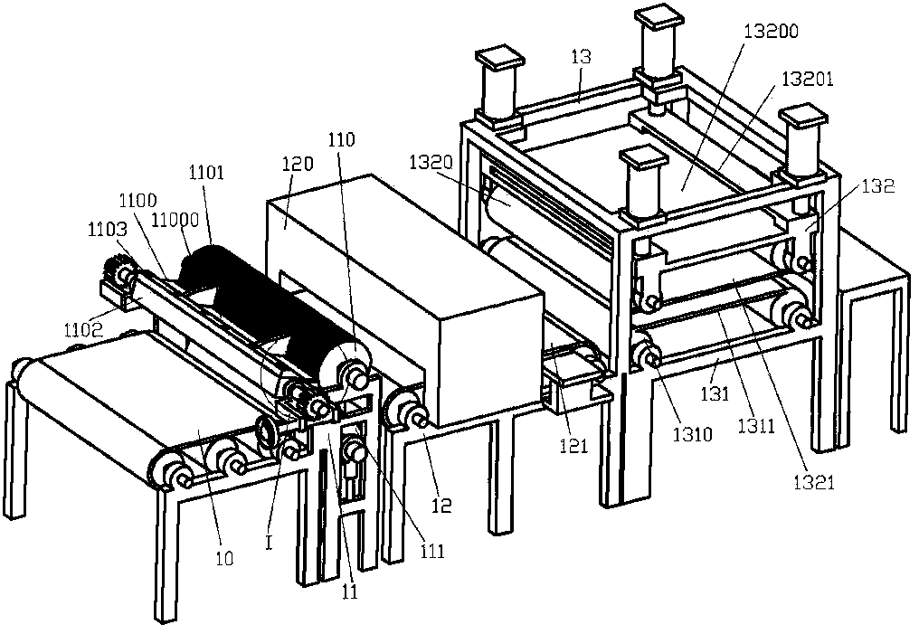
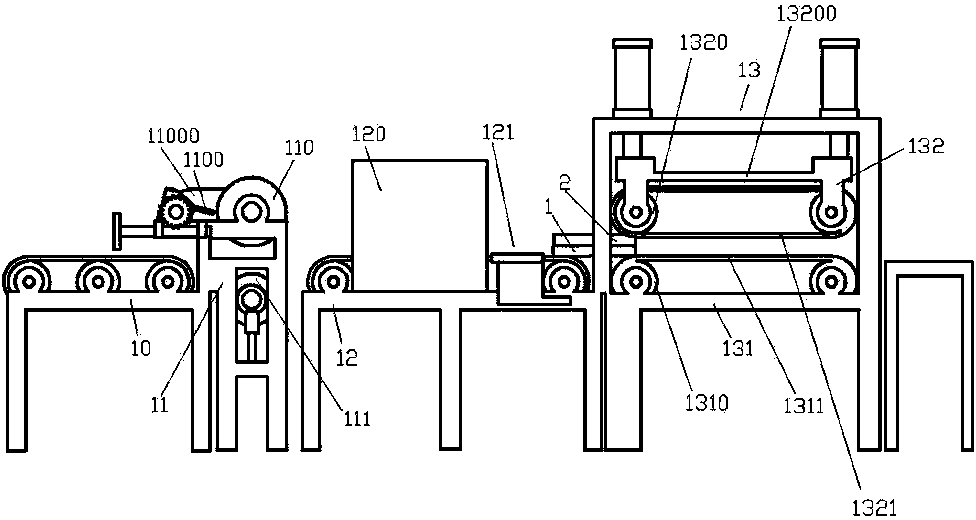
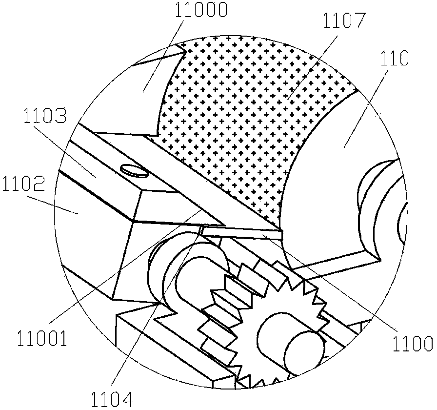
[0029] Example 1, such as figure 1 , 2 , Shown in 3 and 4, a kind of equipment that is used for the production of mattress composite pad core, comprises the feed table 10 that is used to convey composite layer 1, and composite layer 1 can be a layer of material layer in the inner core of mattress Or two or more multi-layer material layers after compounding or other process operations have been carried out. The feeding table 10 includes a stand on which a conveying roller and a conveyor belt driven by the conveying roller are installed on the stand, and are driven by a motor to the conveying roller. The conveyor belt is driven to run, and a gluing table 11 for gluing the upper surface of the composite layer 1 is provided at the outlet of the feeding table 10, and a baking table 12 is provided at the outlet of the gluing table 11, and the baking table 12 also has a corresponding stand , the conveying roller and the conveyor belt driven by the conveying roller are installed ...

Embodiment 2

[0035] Example 2, such as Figure 5 As shown, the difference between it and Embodiment 1 is that there is a thickened layer 13210 on the inner side of the pressing conveyor belt 1321 . The scope of application can be expanded, and it is suitable for effective compounding between layers of various materials.

Embodiment 3

[0036] Example 3, such as Image 6 As shown, the difference between it and Embodiment 1 is that there are three or more pressure rollers 1310 and lower pressure rollers 1320. Here, the description is mainly focused on the case of three, and the situation of more than three is similar to it. When there are three rollers 1310 and lower pressure rollers 1320, it has a better composite effect, and the equipment structure is relatively simple. Through the design of one lower pressure roller 1320 in the middle, the lower pressure conveyor belt 1321 is actually placed on the lower pressure roller. The part below 1320 is divided into two sections, which act on the composite layer 1 and the composite layer 2, and at the same time pass through the middle of the pressure roller 1310 and the lower pressure roller 1320 and the first and last pressure roller 1310 and the lower pressure roller 1320. The effect between the lower pressure roller 1320 and the pressure roller 1310 on the compo...


PUM


Abstract

The invention relates to the technical field of composite machines and particularly relates to a device for producing a composite cushion core of a mattress. The device comprises a feeding table and a gluing table, wherein the feeding table is used for conveying a composite layer I, and the gluing table is located at an outlet of the feeding table and is used for gluing the composite layer I; a baking table is arranged at the outlet end of the gluing table and comprises a baking box and a transition region, wherein the baking box is close to the gluing table, the composite layer I can pass through the baking box, the transition region is located at an outlet of the baking box and is used for stacking the composite layer I and a composite layer II in a counterpoint manner, a composite table is arranged at the outlet end of the transition region and comprises a pressed conveying base frame and a press-down frame, the pressed conveying base frame is located below the composite table, the press-down frame is matched with the pressed conveying base frame and can be lifted, more than two pressed rolls rowed up along the conveying direction are mounted on the pressed conveying base frame, a pressed conveying belt is arranged along the peripheries of the rowed pressed rolls, more than two press-down rolls rowed up along the conveying direction are mounted on the press-down frame, and a press-down conveying belt is arranged along the peripheries of the rowed pressed rolls. The device has the energy-saving and environmentally-friendly effects and is high in efficiency and good in compositing effect.

Description

technical field [0001] The invention relates to the technical field of composite machinery, in particular to a device for producing composite mattress cores for mattresses. Background technique [0002] In the prior art, most of the mattress cores are composed of multi-layer structural layers, which are mainly bonded and connected by gluing and pressing. The connection operation between the layers is basically using manual gluing. , alignment, and pressing to complete the composite work. When mass production is required, the efficiency of manual methods will be relatively low, and the composite effect will be poor and inconsistent. Of course, there are also some mechanical equipment to complete these operations. Here are mainly For gluing and pressing operations, manual methods and existing equipment will cause a lot of waste when using glue, the effect of gluing is not very good, and there are problems such as insufficient gluing and unevenness. The core itself is related ...

Claims


Application Information

Patent Timeline
Patent Type & Authority Applications(China)
IPC IPC(8): B32B37/10B32B37/12B32B38/16
Inventor 胡立江汪富兵李俊
Owner HEYE HEALTH TECH CO LTD
Why Eureka
Try Eureka