
Novel cathode magnetic steel

A magnetic steel and cathode technology, applied in the field of sputtering coating, can solve the problems of insufficient rigidity of the cathode magnetic steel and the influence of the uniformity of the magnetic steel, and achieve the effect of improving the overall stiffness and uniformity

Active Publication Date: 2014-07-23
SHANGHAI NORTH GLASS COATING TECHNOLOGY INDUSTRIAL CO LTD
View PDF6 Cites 0 Cited by
  • Summary
  • Abstract
  • Description
  • Claims
  • Application Information

AI Technical Summary

Problems solved by technology

[0004] The purpose of the present invention is to provide a new type of cathode magnet to solve the problems of insufficient rigidity of the existing cathode magnet and the influence of the uniformity of the magnet.

Method used


Image

  • Novel cathode magnetic steel
  • Novel cathode magnetic steel
  • Novel cathode magnetic steel

Examples


Embodiment approach

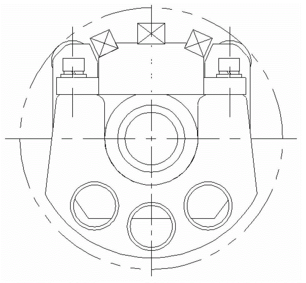
[0028] In the first embodiment of the present invention, please continue to refer to Figure 3 to Figure 7 shown. The above-mentioned supporting base 7 is an aluminum profile supporting base, and an inner cavity is provided on the upper part of the supporting base 7 , which is matched with the magnetic steel assembly 6 , so that the magnetic steel assembly 6 is arranged in the inner cavity of the supporting base 7 .

[0029] In the second embodiment of the present invention, the above-mentioned sealing device 10 is a sealing plate. The magnetic steel assembly 6 is isolated from the outside world by means of a sealing plate installed at both ends of the magnetic steel assembly 6 .

[0030] In the third embodiment of the present invention, several connecting pieces 8 are also included, and the connecting pieces 8 can be screws. Each connecting piece 8 is spaced apart from the lower end of the support base 7 and connected to the magnetic steel assembly 6 , so that the magnetic ...


PUM


Abstract

Novel cathode magnetic steel is disclosed. The cathode magnetic steel comprises a magnetic steel component, and two sealing devices, wherein the magnetic steel component is disposed on a supporting base and is supported through the rigidity of the supporting base; and the two sealing devices are respectively disposed on the two ends of the magnetic steel component so as to seal the magnetic steel component. According to the novel cathode magnetic steel, the magnetic steel component is supported by the aluminum section supporting base, thus effectively enhancing the integral rigidity of the magnetic steel component. The magnetic steel component is installed in the internal cavity of the aluminum section supporting base. Sealing mechanisms such as sealing plates are disposed at the positions of the magnetic component contacting the environment, so that water and impurities cannot enter and the magnetic component is not liable to rust and is free of impurity adsorption. In addition, the magnetic component is fixed through connecting parts such as bolts, and is free of welding of other components, thus effectively enhancing the homogeneity of the magnetic steel.

Description

technical field [0001] The invention relates to the technical field of sputter coating, in particular to a novel cathode magnetic steel capable of binding electrons. Background technique [0002] In the sputtering coating, the magnetron sputtering target adopts a static electromagnetic field, and the magnetic field is in the shape of a curve. After the sputtering chamber is pumped to a certain degree of vacuum, a negative voltage is applied to the cathode, and argon gas is introduced, and glow discharge occurs in the vacuum chamber. , the electrons collide with the argon atoms during the acceleration to the anode under the action of the electric field. If the electrons have enough energy, Ar+ will be ionized and electrons will be generated. The electrons fly to the anode, and Ar+ accelerates to the cathode (sputtering target) under the action of the electric field and bombards the target surface with high energy, causing the target to sputter. In sputtering particles, neut...

Claims


Application Information

Patent Timeline
Patent Type & Authority Applications(China)
IPC IPC(8): C23C14/35
Inventor 李炳坤
Owner SHANGHAI NORTH GLASS COATING TECHNOLOGY INDUSTRIAL CO LTD
Learn More