Fixed-point lifting type bridge erection machine and bridge erection method

A bridge erecting machine and a hoisting technology are applied in the field of fixed-point hoisting bridge erecting machines and bridge erecting to achieve the effects of reduced energy consumption, low energy consumption and safe erection process

Active Publication Date: 2014-07-23
HEBEI UNIV OF TECH
View PDF8 Cites 10 Cited by
  • Summary
  • Abstract
  • Description
  • Claims
  • Application Information

AI Technical Summary

Problems solved by technology

The crane travels on the main girder to hang the girder, and drops the beam after reaching the designated position. Although there is only one host through the hole, the process is simple, but the crane needs to reciprocate and play the role of counterweight to ensure Via implementation

Method used


Image

  • Fixed-point lifting type bridge erection machine and bridge erection method
  • Fixed-point lifting type bridge erection machine and bridge erection method
  • Fixed-point lifting type bridge erection machine and bridge erection method

Examples


Embodiment Construction

[0033] The present invention will be further described below in conjunction with the embodiments and accompanying drawings, and the specific embodiments do not limit the protection scope of the claims of the application.

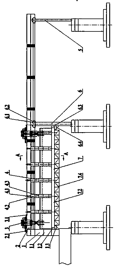
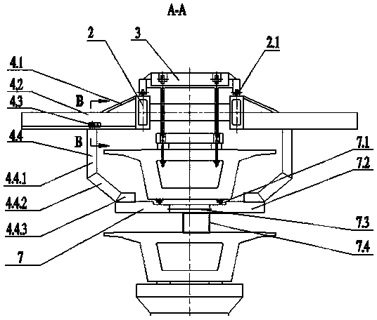
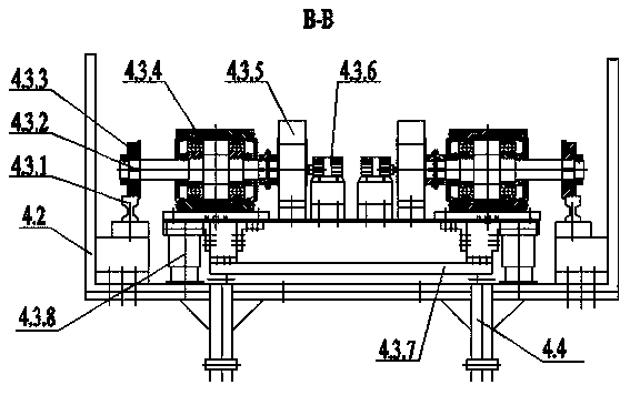
[0034] The fixed-point lifting bridge erecting machine designed by the present invention (bridging machine for short, see figure 1 -4) The design idea is: used for fixed-point lifting bridge erecting machine, two-span structure, push beam design, the push beam uses hydraulic pressure as the power source, pushes the prefabricated box girder to move forward and feed the beam to the designated position, Then carry out the beam lifting, and after the sideways movement of the pushing beam channel is completed, the processes of dropping the beam, closing up and passing the hole will be carried out.

[0035] The bridge erecting machine of the present invention is characterized in that the bridge erecting machine is mainly composed of main girder 2, front outrigger ...


PUM


Abstract

The invention discloses a fixed-point lifting type bridge erection machine and a bridge erection method. The fixed-point lifting type bridge erection machine is characterized by being mainly composed of girders, a front supporting leg, a middle supporting leg, a rear supporting leg, hanging beam overhead travelling cranes, slide arms, a beam pushing channel and a hydraulic and electrical control system, wherein the girders are of a double-span type double-girder structure, the girders are connected through a front group of middle cross connectors, a middle group of middle cross connectors and a rear group of middle cross connectors, and the tops of the girders are provided with overhead travelling crane rails; the hanging beam overhead travelling cranes are installed on the overhead travelling crane rails, and the front supporting leg is fixedly installed below the front ends of the girders; the rear supporting legs are fixedly installed below the tail portions of the girders; the middle supporting leg is installed below the middle portions of the girders of the bridge erection machine; each side arm is composed of an outrigger, a sliding beam, a lateral moving system and a suspension arm, and the side beams are installed on the two outer sides of the girders and are symmetrical about the axis of the bridge erection machine; the upper end of each bottom cross support is connected with a corresponding inclined support, and the lower end of each bottom cross support is fixedly connected with the top surface of a beam pushing bottom plate; the beam pushing channel is composed of two beam pushing rails, a supporting bottom plate, a docking mechanism and an installation truss. The bridge erection method is characterized in that the fixed-point lifting type bridge erection machine is adopted.

Description

technical field [0001] The invention relates to bridge erecting machine technology, in particular to a fixed-point lifting bridge erecting machine and a bridge erecting method which adopts a beam pushing method in the beam feeding process. Background technique [0002] In the construction process of the existing bridge erecting machine, the beam feeding process is mainly carried out by the beam-carrying trolley (in fixed-point lifting) or the crane moves by itself (in non-fixed-point lifting). Regardless of the type of beam feeding process, a high-power motor is required to drive the wheel set to reach the designated position along the established track, and then the beam dropping process is performed. Due to the heavy weight of the prefabricated box girder, the feeding process of the beam is very slow and the efficiency is low; moreover, in non-fixed-point hoisting, the requirements for steel cables are very high, and its maintenance cost also increases accordingly; in addi...

Claims


Application Information

Patent Timeline
Patent Type & Authority Applications(China)
IPC IPC(8): E01D21/00
Inventor 檀润华平恩顺韩波刘晓龙李志张建辉陈子顺于菲
Owner HEBEI UNIV OF TECH
Why Eureka
Try Eureka