Air-operated machine

A technology for wind turbines and fan shafts, which is used in wind turbines, engines, machines/engines, etc., can solve the problems of small wind direction adjustment plate range, small force area of ​​wind blades, and high wind direction requirements, so as to improve reliability and air resistance. The effect of increased, high output power

Inactive Publication Date: 2014-07-23
房勇
View PDF1 Cites 2 Cited by
  • Summary
  • Abstract
  • Description
  • Claims
  • Application Information

AI Technical Summary

Problems solved by technology

[0003] As a kind of clean renewable energy, wind energy is more and more paid attention to by countries all over the world, and the application of wind power generation is also more and more extensive. Among them, there are many studies on wind motors. For example, application number 00119168.3 discloses a wind motor, Including gearbox, wind blade, power output shaft, orientation shaft, adjustment plate and bevel gear, there are two large bevel gears, two small gears, one fixed bevel gear and one movable bevel gear respectively in the gear box , wherein the large bevel gear and the small bevel gear are respectively connected to the fan blades, the fixed bevel gear is connected to the directional shaft, and the moving bevel gear is connected to the power output shaft. The installed adjusting plate can immediately adjust the direction of the wind turbine according to the change of the wind direction, which has achieved the purpose of high efficiency. However, the force bearing area of ​​the fan blade of this invention is small, and the generated moment is small. At the same time, the adjustable range of the wind direction adjusting plate is small. The requirements for wind direction are relatively high.

Method used


Image

  • Air-operated machine
  • Air-operated machine

Examples


Embodiment Construction

[0017] In order to make the technical means, creative features, goals and effects achieved by the present invention easy to understand, the present invention will be further described below in conjunction with specific embodiments.

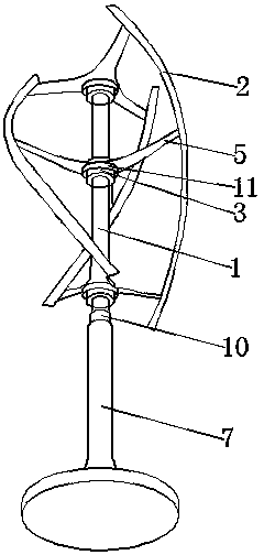
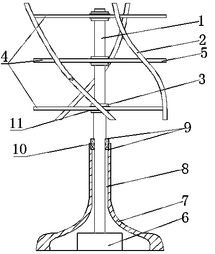
[0018] Such as figure 1 with figure 2 As shown, a kind of wind machine comprises fan shaft 1, blade 2, and described fan shaft 1 is long straight cylindrical rod, and described fan shaft 1 is provided with disc drive machine 3, and described disc drive machine 3 and The support frame 4 is connected, and the support frame 4 is composed of three fan blades 5 placed equidistantly, and the clockwise circular axis offset angle between the adjacent fan blades 5 is 28 ° ~ 32 °, the three support frame 4 Each fan blade 5 is vertically connected to the blade 2 in turn, and the blade 2 is a curved long plate with an airfoil section, and the circumferential angle between the two adjacent blades is 119° to 121°, and the lower end of the fan shaft 1 is provi...


PUM


Abstract

The invention discloses an air-operated machine, and relates to the field of industrial machinery. The air-operated machine comprises a fan shaft and blades. The fan shaft is a long and straight cylindrical rod and is provided with a disc type driver, the disc type driver is connected with a supporting frame composed of three fan blades arranged at equal intervals, the clockwise circumference offset angle between every two adjacent fan blades is 28-32 degrees, and the three fan blades of the supporting frame are sequentially and perpendicularly connected with the blades. The blades are bent long plates with the wing-typed sections, and the circumference angle between every two adjacent blades is 119-121 degrees. An output shaft is arranged at the lower end of the fan shaft. The disc type driver can provide driving force for self-starting of the blades. Due to the wing type design and perpendicular connection of the blades, air resistance in the rotation process can be reduced, the lift force can be increased, the maximum linear speed output is guaranteed, and high output power can be provided. In addition, the structure is simple, and the reliability is high.

Description

technical field [0001] The invention belongs to the field of industrial machinery, in particular to a wind turbine. [0002] Background technique [0003] As a kind of clean renewable energy, wind energy is more and more paid attention to by countries all over the world, and the application of wind power generation is also more and more extensive. Among them, there are many studies on wind motors. For example, application number 00119168.3 discloses a wind motor, Including gearbox, wind blade, power output shaft, orientation shaft, adjustment plate and bevel gear, there are two large bevel gears, two small gears, one fixed bevel gear and one movable bevel gear respectively in the gear box , wherein the large bevel gear and the small bevel gear are respectively connected to the fan blades, the fixed bevel gear is connected to the directional shaft, and the moving bevel gear is connected to the power output shaft. The installed adjusting plate can immediately adjust the dire...

Claims


Application Information

Patent Timeline
Patent Type & Authority Applications(China)
IPC IPC(8): F03D3/00F03D3/06F03D11/00
CPCY02E10/74
Inventor 房勇
Owner 房勇
Why Eureka
Try Eureka