Optical illumination system for linear CCD scanning

A lighting system and linear light source technology, applied in lighting devices, fixed lighting devices, lighting and heating equipment, etc., can solve the problems of high manufacturing cost and use cost, high energy consumption of optical detection equipment, insufficient lighting intensity, etc. The effect of long life, high uniformity and wide resolution range

Active Publication Date: 2014-07-23
CIMS SUZHOU CO LTD
View PDF4 Cites 2 Cited by
  • Summary
  • Abstract
  • Description
  • Claims
  • Application Information

AI Technical Summary

Problems solved by technology

[0003] 1. Use LED light strips to achieve linear spotlight. Because it has high requirements on the uniformity of illumination, the LEDs on each light strip must be strictly screened, and once one of the LEDs fails after use, The entire LED light strip needs to be replaced, which leads to high manufacturing cost and high use cost;
[0004] 2. Use a high-power halogen lamp as the light source to form the required lighting through a complex optical path. The manufacturing cost is high, and the lighting intensity is not enough. It is necessary to increase the power of the halogen lamp (generally 250W) or the number (generally 5) To achieve the necessary brightness, this will inevitably lead to high energy consumption and low energy efficiency of optical detection equipment

Method used


Image

  • Optical illumination system for linear CCD scanning

Examples


Embodiment Construction

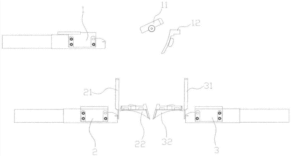
[0022] The present invention will be further elaborated below in conjunction with accompanying drawing and embodiment:

[0023] see figure 1 Shown is the linear CCD scanning optical lighting system for the automatic optical inspection machine of this embodiment, which includes a first linear light source 1, a second linear light source 2, a third linear light source 3, a beam splitter 11, and a second Fresnel lens 21. The third Fresnel lens 31 and the second reflection mirror 22 and the third reflection mirror 32. The first linear light source 1, the second linear light source 2, and the third linear light source 3 irradiate the front, front and rear sides of the detected object at the same time to achieve shadowless lighting. The imaging light reflected by the detected object passes through the beam splitter 11 directly to the CCD linear image sensor. The first linear light source 1, the second linear light source 2, and the third linear light source 3 are all formed by low...


PUM


Abstract

The invention discloses an optical illumination system for linear CCD scanning. The optical illumination system at least comprises a first linear light source, a second linear light source, a third linear light source, a spectroscope, a second Fresnel lens, a third Fresnel lens, a second retroreflector and a third retroreflector. The first linear light source, the second linear light source and the third linear light source are arranged above a detected object and on the front side face and the rear side face of the detected object respectively, and are all horizontally arranged, the right upper surface, the front side face and the rear side face of the detected object are irradiated at the same time, and shadowless lighting is achieved. The first linear light source, the second linear light source and the third linear light source are all formed by matching low-power halogen lamps with optical fibers. The optical illumination system is high in uniformity, large in incident angle and capable of achieving stereoscopic illumination of the front face and the side faces on the detected object, the reflected light of a scanned object directly enters a CCD to be imaged, no optical filter is needed, the resolution range is wide, the limiting requirement for scanned materials is low, the light path structure is simple, energy consumption is low, the energy rate is high, and the service life is long.

Description

technical field [0001] The invention relates to an optical lighting system for linear CCD scanning, which is applied to automatic optical detection equipment for circuit boards, and is specifically used for providing omnidirectional three-dimensional lighting for detected objects during linear CCD scanning, and belongs to the field of electronic manufacturing. Background technique [0002] Most of the existing optical lighting systems for linear CCD scanning used in automatic optical inspection equipment for circuit boards have complex structures and high costs for manufacture and use. There are two main types currently on the market: [0003] 1. Use LED light strips to achieve linear spotlight. Because it has high requirements for uniformity of illumination, the LEDs on each light strip must be strictly screened, and once one of the LEDs fails after use, The entire LED light strip needs to be replaced, which leads to high manufacturing cost and high use cost; [0004] 2. ...

Claims


Application Information

Patent Timeline
Patent Type & Authority Applications(China)
IPC IPC(8): F21S8/00F21V19/00F21V13/12
Inventor 胡冰峰许丽萍周颖慧王旭张志军张剑
Owner CIMS SUZHOU CO LTD
Why Eureka
Try Eureka