Combustion intensifying device in furnace

A combustion device and combustion chamber technology, applied in the direction of combustion method, combustion type, combustion equipment, etc., can solve problems such as easy to emit black smoke, insufficient combustion of domestic waste, etc., and achieve the goals of protecting the environment, reducing operating costs, and reducing workload Effect

Active Publication Date: 2014-07-23
山东威澳环保科技有限公司
View PDF10 Cites 4 Cited by
  • Summary
  • Abstract
  • Description
  • Claims
  • Application Information

AI Technical Summary

Problems solved by technology

[0003] The purpose of the present invention is to provide an intensified combustion device in the furnace to solve the technical pr...

Method used


Image

  • Combustion intensifying device in furnace
  • Combustion intensifying device in furnace
  • Combustion intensifying device in furnace

Examples


Embodiment Construction

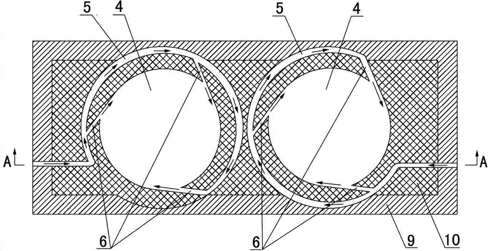
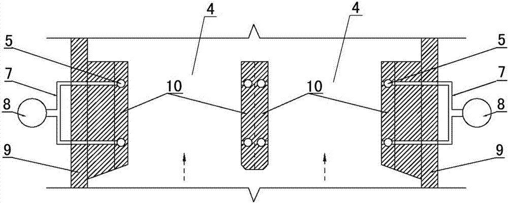
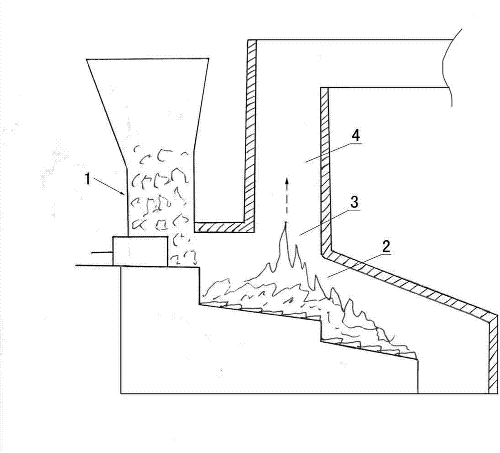
[0022] Examples see Figure 1-3 As shown, this intensified combustion device in the furnace is arranged on the fire outlet 3 of the first combustion chamber 2 of the mechanical grate type domestic waste incinerator 1, including the second combustion chamber wall, the second combustion chamber located inside the second combustion chamber wall chamber, and the oxygen fan 8 positioned outside the wall of the second combustion chamber.

[0023] The second combustion chamber is composed of two cylindrical strong combustion chambers 4, the bottom of the strong combustion chamber 4 communicates with the first combustion chamber 2 through the fire outlet 3, and the top of the strong combustion chamber 4 communicates with the waste heat boiler.

[0024] The wall body of the second combustion chamber is provided with a turbulent oxygen delivery channel, which includes an annular oxygen delivery channel 5 and three tangential oxygen injection channels 6 uniformly distributed along the ci...


PUM


Abstract

A combustion intensifying device in a furnace comprises two combustion chamber walls, two combustion chambers on the inner sides of the two combustion chamber walls, and oxygen supply fans located on the outer sides of the two combustion chamber walls. Each combustion chamber is composed of at least two cylindrical combustion intensifying chambers, the bottoms of the combustion intensifying chambers are communicated with one combustion chamber through fire outlets, and the tops of the combustion intensifying chambers are communicated with a waste heat boiler; turbulence oxygen supply channels are formed in the two combustion chamber walls, each turbulence oxygen supply channel comprises an annular oxygen conveying channel and a tangential oxygen spray channel, air outlets of the tangential oxygen spray channels are communicated with the combustion intensifying chambers, and air inlets of the tangential oxygen spray channels are communicated with oxygen supply fans on the outer sides of the two combustion chamber walls through the annular oxygen conveying channels. According to the device, a traditional combustion intensifying chamber with a rectangular section is replaced by multiple cylindrical combustion intensifying chambers, meanwhile, oxygen is supplied to the combustion intensifying chambers tangentially through the tangential oxygen spray channels so that the defects that two combustion chambers of a mechanical fire grate type domestic garbage incinerator is insufficient in combustion and black smoke is prone to being generated can be overcome, the aim of treatment from sources is achieved, and environment is protected.

Description

technical field [0001] The invention relates to an intensified combustion device used in domestic waste incinerators. Background technique [0002] The second combustion chamber in the mechanical grate type domestic waste incinerator (including imported technology) currently used in the society (see the Figure 4 ), which is a vertical space with a rectangular section (that is, the cross-sectional shape of the second combustion chamber is a rectangle), and in order to supplement the oxygen in the second combustion chamber, the vertical space with a rectangular section is installed on the front and rear walls along the width direction of the furnace Multiple jets for oxygenation. After years of practice, it has been proved that the high-temperature flue gas in the secondary combustion chamber of this structure cannot be fully mixed with the supplementary oxygen, and there is a low-temperature dead angle, which cannot completely burn the combustibles and achieve full combustio...

Claims


Application Information

Patent Timeline
IPC IPC(8): F23G5/44F23L9/00
Inventor 苏永强王学江
Owner 山东威澳环保科技有限公司
Why Eureka
Try Eureka