A combined fireworks outer tube

A technology combining fireworks and outer cylinders, which is applied in pyrotechnics, offensive equipment, weapon types, etc., can solve the problems that the propellant combustion chamber cannot be sealed strictly, damage the integrity of the outer cylinder body structure, and inconsistent launch heights, etc., and achieve reliable Efficient mechanized production, avoiding emission energy loss, and realizing the effect of mechanized production

Active Publication Date: 2015-12-09
詹昌枣
View PDF5 Cites 0 Cited by
  • Summary
  • Abstract
  • Description
  • Claims
  • Application Information

AI Technical Summary

Problems solved by technology

The disadvantages are that, first, the propellant combustion chamber cannot be tightly sealed, resulting in a waste of the working energy of the combustion gas, resulting in an excessively large amount of propellant, and excessive smoke generated by the combustion of the propellant, polluting the environment
Second, the traditional lead structure has complicated processing technology and low production efficiency
The insertion process needs to insert the two ends of the soft lead wire into the small holes of the two adjacent cylinders respectively, which is difficult to achieve reliable and efficient mechanized production
Third, the existing products are prone to cross-fire phenomenon: that is, the gunpowder and effect parts in the cavity of each outer cylinder are not sequentially ignited and fired by the fuse according to the designed discharge procedure, but two or more outer cylinders are fired almost simultaneously. situation, completely destroying the discharge effect
Fourth, the existing products need to drill holes in the side wall of the outer cylinder to insert and spread the fire, but the integrity of the organizational structure of the outer cylinder is destroyed, and the phenomenon of cracking the cylinder is prone to occur, which poses a safety hazard and leads to inconsistent launch heights

Method used


Image

  • A combined fireworks outer tube
  • A combined fireworks outer tube

Examples


Embodiment Construction

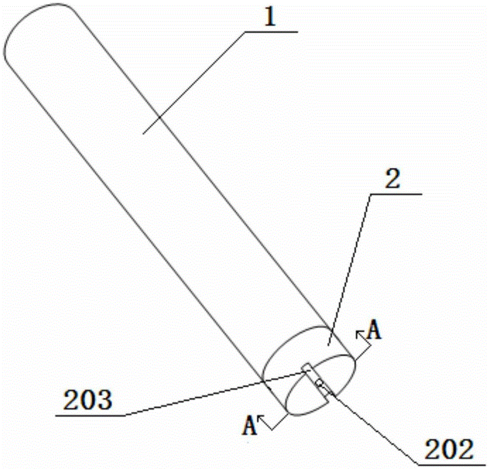
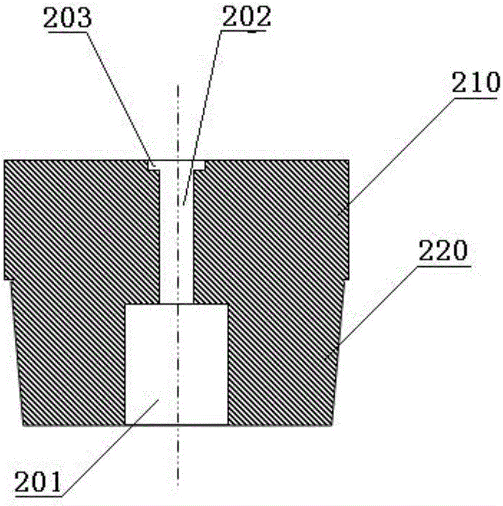
[0009] Referring to the accompanying drawings, which reflect a specific structure of the present invention, the combined fireworks outer cylinder is composed of a cylinder body 1 and a bottom plug 2 fixed at the bottom of the cylinder body 1, and the center position of the upper part of the bottom plug 2 is provided with a launcher. Drug chamber 201, the center of the firing chamber 201 is provided with an overfire hole 202 that runs through the lower part of the bottom plug 2, and the upper port of the fire through hole 202 passes through the firing chamber 201; the bottom end surface of the bottom plug 2 is provided with a lead wire that traverses the bottom end surface The installation groove 203 and the lower port of the fire through hole 202 pass through the lead wire installation groove 203; the bottom plug 2 is composed of a cylindrical seat body 210 and a frustum-shaped insert body 220. Sealing gunpowder is installed in the through-hole 202, and the sealing powder is co...


PUM


Abstract

The invention discloses a combined firework outer barrel. The combined firework outer barrel is composed of a barrel body and a bottom plug which is fixedly arranged at the bottom end of the barrel body. The bottom plug is provided with a propellant powder cavity and a fire passing through hole, a lead wire mounting groove which traverses the bottom end face is formed in the bottom end face of the bottom plug, and a lower end opening of the fire passing through hole is communicated with the lead wire mounting groove. A sealed starting mix is arranged in the fire passing through hole. The sealed starting mix consists of, by weight, 40 parts of potassium nitrate, 50 parts of activated carbon, five parts of sulphur and five parts of charcoal. Densely-expanded solid remains can be formed after the sealed starting mix is burnt, and the fire passing through hole is plugged so as to seal the bottom end of the propellant powder cavity. Firing energy loss can be effectively avoided, the cross-firing phenomenon and the barrel cracking phenomenon are eradicated, the technology is greatly simplified, and reliable and efficient mechanized production can be better achieved.

Description

technical field [0001] The invention relates to a fireworks outer tube for making combined fireworks or ground fireworks. Background technique [0002] Combined fireworks are also called ground fireworks and potted flowers. Its structure is fixed in parallel with several outer cylinders made of paper. The bottom of the outer cylinder is closed with a mud bottom. Connect the ignition lead. Its disadvantages are, first, the propellant combustion chamber cannot be tightly sealed, resulting in waste of working energy of the combustion gas, resulting in excessive filling of the propellant, excessive smoke generated by the combustion of the propellant, and polluting the environment. Second, the processing technology of the traditional lead wire structure is complicated and the production efficiency is low. In addition to cutting and drawing, each paper cylinder needs to be punched twice, and then inserted and drawn, which is now mainly done by hand. The insertion process needs...

Claims


Application Information

Patent Timeline
Patent Type & Authority Patents(China)
IPC IPC(8): F42B4/00
Inventor 詹昌枣
Owner 詹昌枣
Why Eureka
Try Eureka