
Temperature sensor based on hollow annular waveguide optical fiber

A technology of temperature sensor and ring waveguide, which is applied in the coupling of optical waveguide, thermometers with physical/chemical changes, thermometers, etc., can solve the problems of increasing structural instability, high reflectivity requirements, and low sensitivity of temperature sensors. Achieve the effect of realizing quasi-distribution measurement and improving temperature sensitivity

Active Publication Date: 2014-07-23
HARBIN ENG UNIV
View PDF3 Cites 16 Cited by
  • Summary
  • Abstract
  • Description
  • Claims
  • Application Information

AI Technical Summary

Problems solved by technology

The sensitivity of temperature sensors based on fiber Bragg gratings is low, about 0.01nm / ℃; the sensitivity of temperature sensors based on long-period fiber gratings and various core mode-cladding mode interferences is slightly lower than that of fiber Bragg grating temperature sensors. High, but generally only about 0.1nm / ℃; the temperature sensor based on the Fabry-Perot interferometer requires high reflectivity at both ends of the sensing fiber; the temperature sensor based on the dual-core photonic crystal fiber requires the photonic crystal fiber Bending pretreatment increases the instability of the structure

Method used


Image

  • Temperature sensor based on hollow annular waveguide optical fiber
  • Temperature sensor based on hollow annular waveguide optical fiber
  • Temperature sensor based on hollow annular waveguide optical fiber

Examples


Embodiment Construction

[0017] The present invention will be further described below with examples in conjunction with the accompanying drawings, but the protection scope of the present invention should not be limited by this.

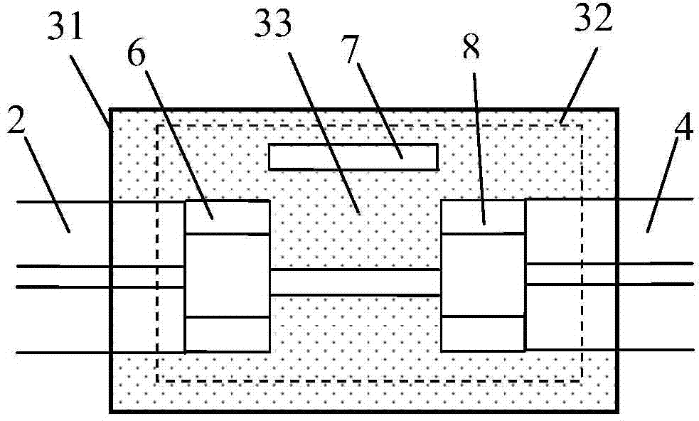
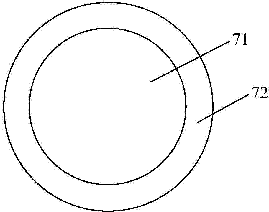
[0018] combine figure 1 and figure 2 , a kind of temperature sensor based on hollow ring waveguide fiber of the present invention, comprises broadband light source 1, input single-mode optical fiber 2, optical fiber sensing head 3, output single-mode optical fiber 4 and spectrum analyzer 5; Optical fiber sensing head 3 One end is connected to the light source 1 through the input single-mode optical fiber 2, and the other end is connected to the spectrum analyzer 5 through the output single-mode optical fiber 4; the optical fiber sensing head 3 is composed of a capillary 31, an optical fiber Mach-Zehnder interferometer 32 packaged in the capillary and Composed of high thermo-optic coefficient liquid 33; optical fiber Mach-Zehnder interferometer 32 is composed of input single...


PUM


Abstract

The invention provides a temperature sensor based on a hollow annular waveguide optical fiber. One end of an optical fiber sensing head is connected with a light source through an input single-mode optical fiber, and the other end of the optical fiber sensing head is connected with an optical spectrum analyzer through an output single-mode optical fiber. The optical fiber sensing head is composed of a capillary tube, an optical fiber Mach-Zehnder interferometer packaged in the capillary tube and liquid with a high thermo-optical coefficient. The optical fiber Mach-Zehnder interferometer comprises an input multi-mode optical fiber, the hollow annular waveguide optical fiber and an output multi-mode optical fiber, wherein the input multi-mode optical fiber is fused with the input single-mode optical fiber in an axis alignment mode, the output multi-mode optical fiber is fused with the output single-mode optical fiber in an axis alignment mode, the hollow annular waveguide optical fiber is fused with the input multi-mode optical fiber and the output multi-mode optical fiber in an axis staggering mode, the staggering distance between the optical fiber axes is larger than the wall thickness of the hollow annular waveguide optical fiber, and air holes of the hollow annular waveguide optical fiber are filled with the liquid with the high thermo-optical coefficient. Through the air holes of the hollow annular waveguide optical fiber and two light beams transmitted by the annular waveguide, the temperature can be measured, and the temperature sensor is compact in structure and high in sensitivity.

Description

technical field [0001] The invention relates to an optical fiber temperature sensor, in particular to a temperature sensor based on a hollow ring waveguide optical fiber. Background technique [0002] Optical fiber temperature sensors have been extensively studied due to their advantages of small size, fast response, corrosion resistance, and electromagnetic interference resistance, and a variety of optical fiber sensors with different structures have been used for temperature measurement. These structures are mainly based on fiber Bragg gratings, long-period fiber gratings, Fabry-Perot interferometers, dual-core photonic crystal fibers and various structures based on core mode-cladding mode interference. The sensitivity of temperature sensors based on fiber Bragg gratings is low, about 0.01nm / ℃; the sensitivity of temperature sensors based on long-period fiber gratings and various core mode-cladding mode interferences is slightly lower than that of fiber Bragg grating tempe...

Claims


Application Information

Patent Timeline
IPC IPC(8): G01K11/32G02B6/255G02B6/032G01K11/3206
Inventor 周爱张亚勋许全杨军苑立波
Owner HARBIN ENG UNIV
Learn More