Supercharge Your Innovation With Domain-Expert AI Agents!

Method of observing samples with a fluorescent microscope

A fluorescence microscope and electron microscope technology, applied in the field of observing samples with a fluorescence microscope, can solve the problems of destroying samples, damage, etc.

Inactive Publication Date: 2014-07-23
FEI COMPANY
View PDF6 Cites 2 Cited by
  • Summary
  • Abstract
  • Description
  • Claims
  • Application Information

AI Technical Summary

Problems solved by technology

[0010] The problem when using intense irradiation is that heating can occur which can damage or destroy the sample

Method used


Image

  • Method of observing samples with a fluorescent microscope
  • Method of observing samples with a fluorescent microscope
  • Method of observing samples with a fluorescent microscope

Examples


Embodiment Construction

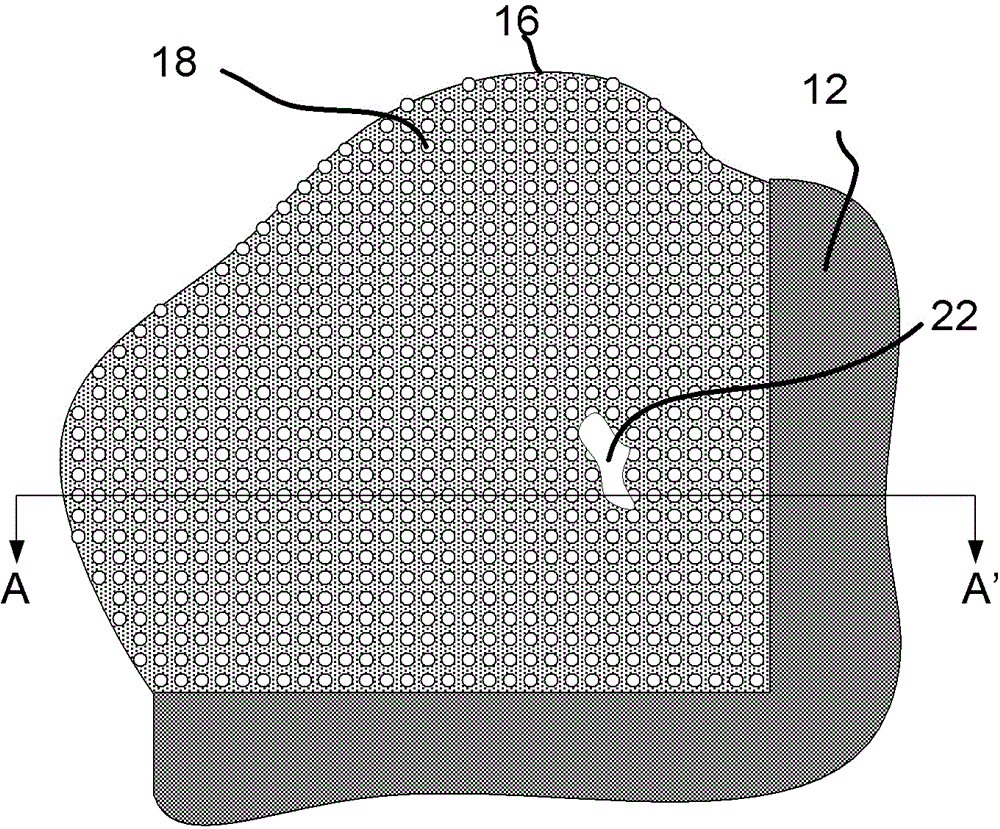
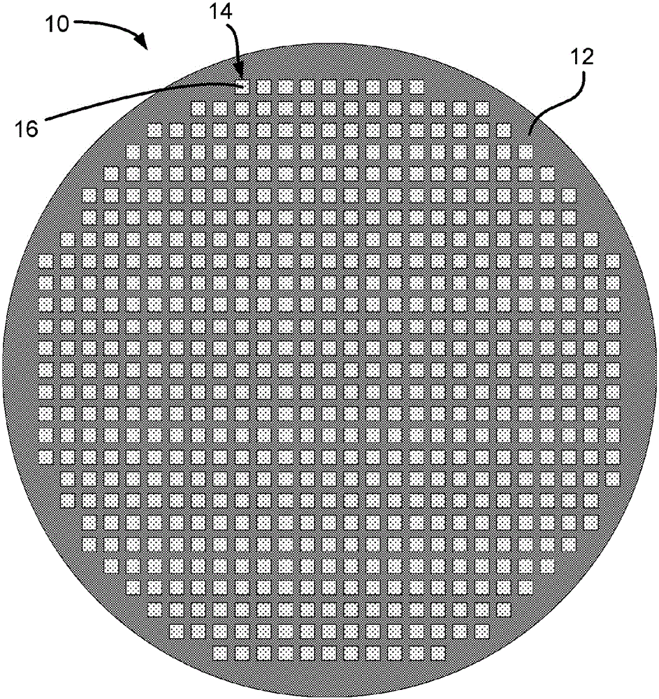
[0037] Figure 1A The top view of the TEM grid is schematically shown.

[0038] TEM grid 10 is a circular thin copper foil (copper foil) 12 with a thickness of about 25 μm and a diameter of 3.05 mm. The foil exhibits a large number of holes 14 (eg 400 per inch) and a thin carbon film 16 on which a sample can be placed. Copper and carbon not only provide support but also conductivity to avoid charging.

[0039] Note that grids with coarser or finer meshes, other materials (gold, nickel, (carbon-coated) plastics), other forms of holes (slots, hexagons) or Forms other than thin circular foils (see eg US Patent Nos. US 7,767,979 and US 7,034,316).

[0040] Note also that the holes may exhibit thin carbon layers, eg 3 nm layers. This is based on the fact that LARSON is not sufficient to absorb light or provide a conductive path from the sample to ground (the holder of the grid).

[0041] The film does not have to be a carbon film, essentially for the present invention the fil...


PUM


Abstract

The invention discloses a method of observing samples with a fluorescent microscope. The invention relates to a method of inspecting parts of a sample on a TEM grid (12) with a fluorescence microscope, as arises when performing correlative microscopy, more specifically for samples on a holey carbon grid. A problem occurs when imaging vitrified ice (20) with sample material (22) when the ice is heated by the light used. The invention is based on the insight that the absorption in the carbon support film (16) is responsible for the heating, as ice hardly absorbs light. By localizing the illumination of the fluorescent microscope to the parts of the sample that are above a hole (18) in the carbon, heating of the ice is lowered. The localization can be achieved by, for example, passing the light through a LCD type Spatial Light Modulator.

Description

technical field [0001] The present invention relates to a method of examining a portion of a sample, at least partially supported by a supporting carbon film, with a fluorescence microscope, which irradiates the sample with excitation light to produce fluorescence or phosphorescence, said sample being susceptible to damage caused by an increase in temperature Induced damage, the supported carbon film exhibits holes or thickness variations. Background technique [0002] From SCHWARTZ Cindy L et al in "Cryo-fluorescence microscopy facilitates correlations between light and cryo-electron microscopy and reduces the rate of photobleaching" in J. Microsc. 2007 Aug 227 (Pt 2), pp. 98–109 This method is known. [0003] Known methods describe, in a setup for cryo-fluorescence microscopy, illuminating a cryo-vitrified sample with light and observing the fluorescence. [0004] A cryogenic vitrified sample is, for example, a biological sample that is frozen to arrest the sample in a g...

Claims


Application Information

Patent Timeline
IPC IPC(8): G01N21/64
CPCG02B21/082G02B21/16G01N21/6458
Inventor B.布伊斯塞L.F.范德里伊
Owner FEI COMPANY
Features
  • R&D
  • Intellectual Property
  • Life Sciences
  • Materials
  • Tech Scout
  • Unparalleled Data Quality
  • Higher Quality Content
  • 60% Fewer Hallucinations
Learn More