
Test device for acquiring on-off state of thyristor impulse power switch assembly

A technology of pulse power switch and on-off state, which is applied in the field of electronic power, can solve the problems affecting the reliability and safety of pulse power switch components, and achieve the effect of reliable operation

Active Publication Date: 2014-07-23
BEIJING ANTAIZHICHENG SCI & TECH DEV
View PDF8 Cites 10 Cited by
  • Summary
  • Abstract
  • Description
  • Claims
  • Application Information

AI Technical Summary

Problems solved by technology

A large number of engineering practices have shown that when thyristors are used as pulse power switching components, open-circuit faults of thyristor components that do not conduct due to drive circuit failures, or short-circuit faults of thyristor components that are directly connected due to overheating breakdown due to long-term strong current In addition, there are a small number of short-circuit failures caused by overvoltage breakdown of thyristor components.
Both of these failures will directly affect the reliability and safety of the pulse power switch components.

Method used


Image

  • Test device for acquiring on-off state of thyristor impulse power switch assembly
  • Test device for acquiring on-off state of thyristor impulse power switch assembly
  • Test device for acquiring on-off state of thyristor impulse power switch assembly

Examples


Embodiment Construction

[0029] Embodiments of the present invention are described in detail below, examples of which are shown in the drawings, wherein the same or similar reference numerals designate the same or similar elements or elements having the same or similar functions throughout. The embodiments described below by referring to the figures are exemplary and are intended to explain the present invention and should not be construed as limiting the present invention.

[0030] In the present invention, unless otherwise clearly specified and limited, terms such as "installation", "connection", "connection" and "fixation" should be understood in a broad sense, for example, it can be a fixed connection or a detachable connection , or integrally connected; it may be mechanically connected or electrically connected; it may be directly connected or indirectly connected through an intermediary, and it may be the internal communication of two components. Those of ordinary skill in the art can understand...


PUM


Abstract

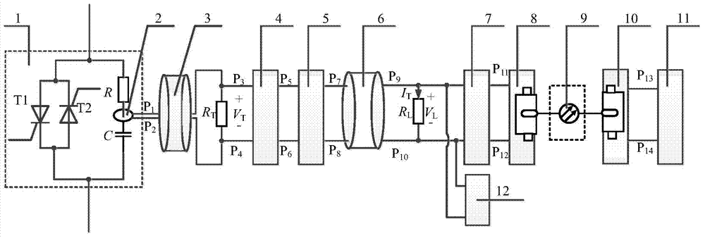
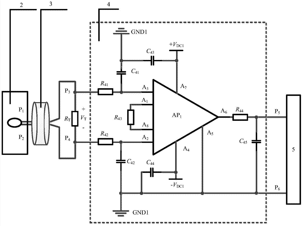
The invention provides a test device for acquiring the on-off state of a thyristor impulse power switch assembly. The test device comprises a current sensor, a preprocessing circuit, a constant current source conversion circuit, a sampling resistor, a shaping and comparing circuit, a data collector, an electro-optic conversion circuit, a photovoltaic conversion circuit and a control module. The current sensor is arranged in a resistance-capacitance absorption circuit of a thyristor assembly in a sleeved mode. The input end of the preprocessing circuit is connected with the current sensor through a first double-core shielding double-twisted cable. The input end of the constant current source conversion circuit is connected with the output end of the preprocessing circuit. The input end of the shaping and comparing circuit is connected with the two ends of the sampling resistor. The input end of the data collector is connected with the two ends of the sampling resistor. The input end of the electro-optic conversion circuit is connected with the output end of the shaping and comparing circuit. The input end of the photovoltaic conversion circuit is connected with the output end of the electro-optic conversion circuit through a cable. The control module is connected with the output end of the photovoltaic conversion circuit. According to the test device, the work state of the impulse power switch assembly can be monitored fast, reliably and safely, state signals can be transmitted in a long distance, and the test device can adapt to a strong electromagnetic environment occasion.

Description

technical field [0001] The invention relates to the technical field of electronic power, in particular to a test device for obtaining the on-off state of a thyristor pulse power switch assembly. Background technique [0002] At present, power electronics technology has developed to a very high level. High-voltage and high-power power electronic devices, such as IGBT (Insulated Gate Bipolar Transistor, insulated gate bipolar transistor), power MOSFET (Metal-Oxide-Semiconductor Field-Effect Transistor, metal-oxide layer semiconductor field effect transistor), GTO (Gate Turn-Off Thyristor, the gate can turn off the thyristor), thyristor SCR (silicon controlled rectifier), IGCT (Integrated Gate Commutated Thyristors, integrated gate commutated thyristor), MAGT (MOS Gate control-thyristor) and IEGT (Injection Enhanced Gate Transistor, electron injection enhanced gate transistor) have been successfully developed and used in a large number of projects, further promoting the develop...

Claims


Application Information

Patent Timeline
Patent Type & Authority Applications(China)
IPC IPC(8): G01R31/327
Inventor 宋晓龙胡瀚文陈俐钧张志国苏英杰
Owner BEIJING ANTAIZHICHENG SCI & TECH DEV
Learn More