
Thermal management system for new energy vehicle and new energy vehicle

A thermal management system and technology for new energy vehicles, applied in the field of new energy vehicles, can solve the problems of complex structure, waste of energy, insufficient utilization of waste heat, etc., and achieve the effects of simple pipeline arrangement, simple system and healthy operation.

Inactive Publication Date: 2022-03-11
珠海中车装备工程有限公司
View PDF0 Cites 0 Cited by
  • Summary
  • Abstract
  • Description
  • Claims
  • Application Information

AI Technical Summary

Problems solved by technology

[0003] The current thermal management system of electric vehicles includes air-conditioning system, motor cooling system, and battery temperature control system. Insufficient utilization, such as battery waste heat, motor waste heat and heat generated by compressor power consumption, is directly discharged into the environment, resulting in energy waste

Method used


Image

  • Thermal management system for new energy vehicle and new energy vehicle
  • Thermal management system for new energy vehicle and new energy vehicle
  • Thermal management system for new energy vehicle and new energy vehicle

Examples


Embodiment 1

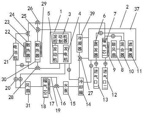
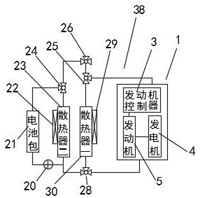
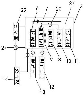
[0030] Refer to the attached Figure 1-5 , a thermal management system for a new energy vehicle of this embodiment and a new energy vehicle, including a heat source assembly 1, an assembly 37, an assembly heat dissipation system 2, a first heat collection system 38, a battery pack heat dissipation system 34 and an engine Heat dissipation system 35, the assembly heat dissipation system 2 includes evaporator 6, heating core one 7, blower fan 8, mixer 10, filter 11, cooling box 14, condenser 39, three-way valve one 27 and solenoid valve 20, the evaporator 6 and the heating core one 7 are connected to the mixer 10, the heating core one 7 is connected to the heater one 9, the mixer 10 is connected to the blowing fan 8 and the filter 11, and the cooling The tank 14 communicates with the condenser 39 and the assembly 37 through the three-way valve one 27, and the first heat collection system 38 includes the engine controller 3, the engine 5, the generator 4, the radiator one 30, and ...

Embodiment 2

[0040] Refer to the attached Figure 6-7 , and the difference from Embodiment 1 is that: the first heat collection system 38, radiator three 32 and heater five 33 form a second heat collection system 36, the radiator three 32 communicates with heater five 33, and the heat dissipation The third device 32 is connected to the battery pack 21.

[0041] The specific implementation scenarios are:

[0042] When those skilled in the art use the present invention, when the heat source assembly 1 composed of the engine controller 3, the generator 4 and the engine 5 is radiated and cooled, the coolant in the cooling box 14 flows through the heat source assembly 1 to cool the heat source assembly 1, The coolant flows through the three-way valve three 25, the three-way valve four 26 and the condenser 39, and finally returns to the cooling box 14; when cooling the battery pack 21, the coolant in the cooling box 14 flows through the water pump 15, the three-way Valve six 16, bypass pipe 19...


PUM


Abstract

The invention belongs to the technical field of new energy vehicles, in particular to a heat management system for a new energy vehicle and the new energy vehicle, and adopts the technical scheme that the heat management system comprises a heat source assembly, an assembly, an assembly heat dissipation system, a first heat collection system, a battery pack heat dissipation system and an engine heat dissipation system, the assembly heat dissipation system comprises an evaporator, a first heating core, a blowing fan, a mixer, a filter, a cooling box, a condenser, a first three-way valve and an electromagnetic valve, and the evaporator and the first heating core are both communicated with the mixer. And the battery pack heat dissipation system and the engine heat dissipation system share the cooling box, so that pipeline arrangement is simple, the structure is simplified, waste heat of the engine controller, the generator and the engine is effectively recycled, energy consumption is reduced, and the cruising ability of the automobile is enhanced.

Description

technical field [0001] The invention relates to the technical field of new energy vehicles, in particular to a thermal management system for new energy vehicles and the new energy vehicles. Background technique [0002] New energy vehicles refer to vehicles that use unconventional vehicle fuels as the power source, integrate advanced technologies in vehicle power control and drive, and form vehicles with advanced technical principles, new technologies, and new structures. New energy vehicles include four types Hybrid electric vehicles, pure electric vehicles, fuel cell electric vehicles, other new energy vehicles, etc. Unconventional vehicle fuels refer to fuels other than gasoline, diesel, natural gas, liquefied petroleum gas, ethanol gasoline, methanol, and dimethyl ether , the definition of new energy vehicles: different countries have different formulations, which are usually called "low pollution vehicles" in Japan. Popularization Action Plan", the plan refers to low-p...

Claims


Application Information

Patent Timeline
Patent Type & Authority Applications(China)
IPC IPC(8): B60H1/00B60H1/04B60H1/14B60K11/02
CPCB60H1/00278B60H1/00385B60H1/04B60H1/143B60K11/02B60H2001/00307
Inventor 张海清王海华张为阳戴光伟吴维智
Owner 珠海中车装备工程有限公司
Learn More