Position identifying method and device of mask plate polluted area

A technology of polluted areas and marking devices, which is applied in the field of position marking methods and devices for mask polluted areas, can solve the problems of low cleaning efficiency in clean areas, and achieve the effect of improving cleaning efficiency

Inactive Publication Date: 2014-07-23
BOE TECH GRP CO LTD +1
View PDF6 Cites 11 Cited by
  • Summary
  • Abstract
  • Description
  • Claims
  • Application Information

AI Technical Summary

Problems solved by technology

[0006] The embodiment of the present invention provides a method and device for identifying the position of the contaminated area of ​​the mask, which is used to solve the problem of low cleaning efficiency caused by the inability to accurately locate the area to be cleaned on the mask in the prior art

Method used


Image

  • Position identifying method and device of mask plate polluted area
  • Position identifying method and device of mask plate polluted area
  • Position identifying method and device of mask plate polluted area

Examples


Embodiment Construction

[0032] Embodiments of the present invention provide a method and device for identifying the position of a contaminated area on a mask, which is used to solve the problem of low cleaning efficiency in the prior art due to the inability to accurately locate the area to be cleaned on the mask.

[0033] The following will clearly and completely describe the technical solutions in the embodiments of the present invention with reference to the accompanying drawings in the embodiments of the present invention. Obviously, the described embodiments are only some of the embodiments of the present invention, not all of them. Based on the embodiments of the present invention, all other embodiments obtained by persons of ordinary skill in the art without making creative efforts belong to the protection scope of the present invention.

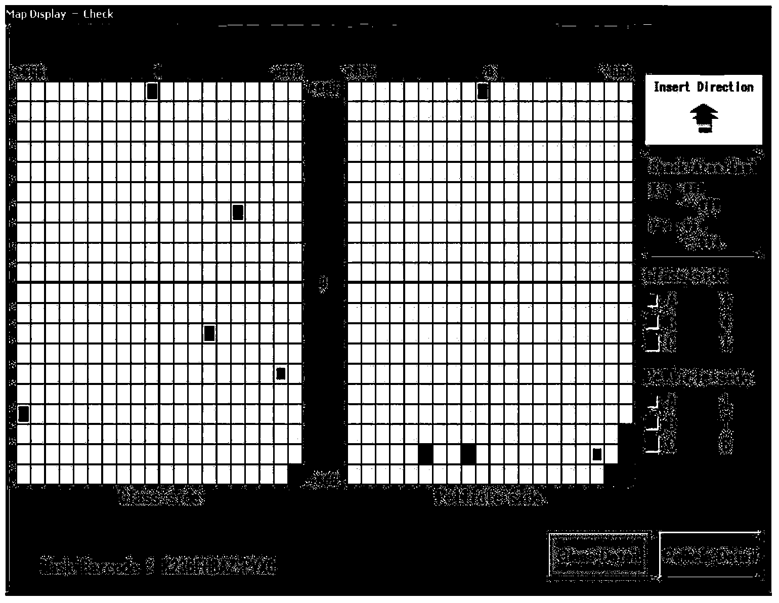
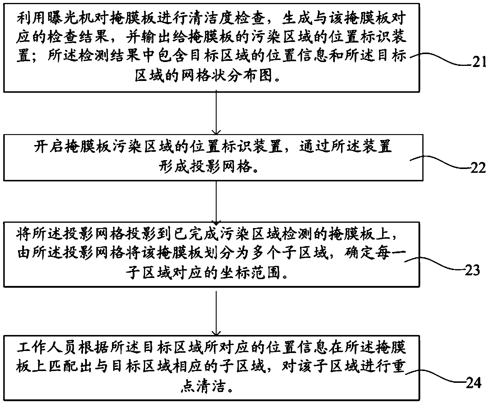
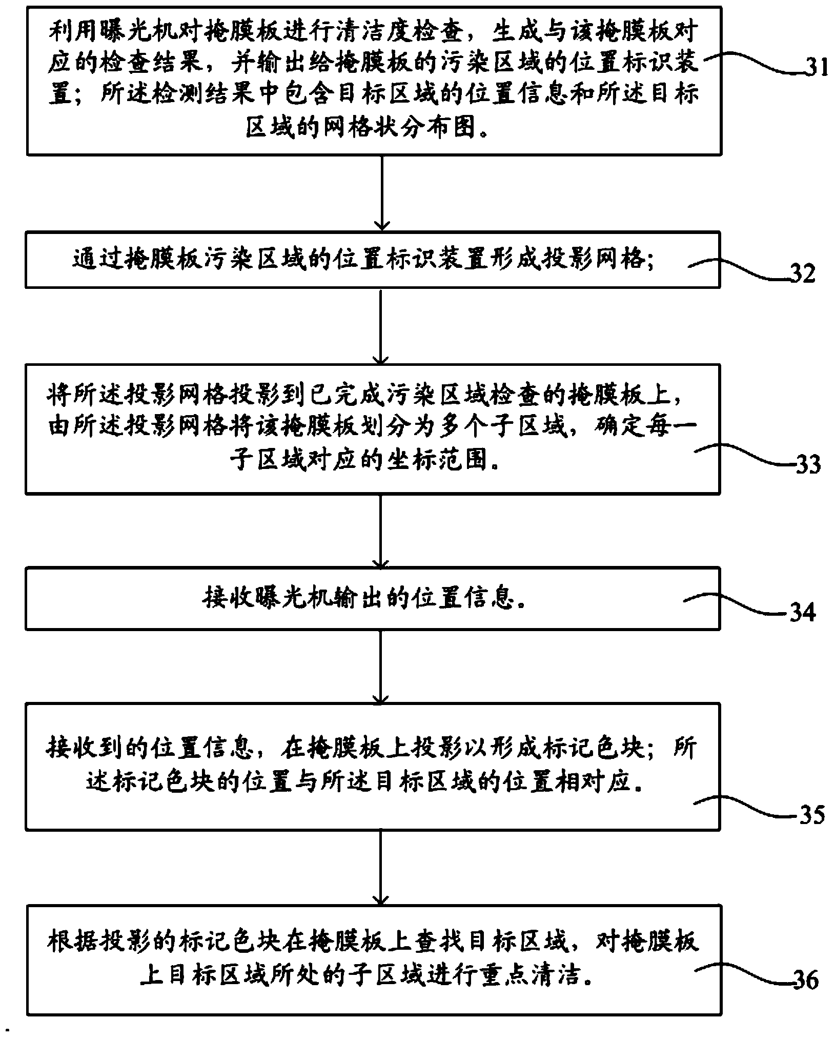
[0034] Embodiment 1 of the present invention provides a method for identifying the position of a contaminated area on a mask, including:

[0035] Form a proje...


PUM


Abstract

The invention provides a position identifying method and device of a mask plate polluted area, which aim at solving the problem of low cleaning efficiency caused by the fact that an area required to be cleaned cannot be positioned on a mask plate accurately in the prior art. The method comprises the following steps: forming a projection grid; projecting the projection grid on a mask plate; dividing the mask plate into a plurality of sub areas by the projection grid, determining a coordinate range of each sub area, and matching sub areas corresponding to a target area on the mask plate according to position information corresponding to the target area by users, wherein the position information corresponding to the target area is obtained by examining the polluted area of the mask plate by an exposure machine in advance, and is contained in an examined result output by the exposure machine.

Description

technical field [0001] The invention relates to the technical field of semiconductor manufacturing, in particular to a method and device for marking the position of a contaminated area of ​​a mask. Background technique [0002] In the production process of Thin Film Transistor Liquid Crystal Display (TFT-LCD) devices, in the exposure process of the array process, it is necessary to use a mask to expose the substrate. The mask is used in the exposure process. A very important component, the cleanliness of the mask directly affects the yield of the product. [0003] However, the mask board is very susceptible to particle contamination during use, transportation and storage; among them, the particle contamination on the upper surface of the mask board (Blank Face) is higher than that of the lower surface (Pellicle Face). ) pollution can affect the quality of the exposure process. [0004] If the particle-contaminated mask is used in the exposure process, it will cause repeate...

Claims


Application Information

Patent Timeline
Patent Type & Authority Applications(China)
IPC IPC(8): G03F1/82G03F1/38
Inventor 刘明悬郭总杰刘正张治超张小祥
Owner BOE TECH GRP CO LTD
Why Eureka
Try Eureka