
Touch panel

A technology of touch panel and touch sensing, which is applied in the direction of instrument, electrical digital data processing, input/output process of data processing, etc. It can solve the problems of short circuit of sensing electrodes, inability to completely separate sensing electrodes, etc., and achieve beautification The effect of appearance

Inactive Publication Date: 2014-07-23
WINTEK CORP
View PDF5 Cites 16 Cited by
  • Summary
  • Abstract
  • Description
  • Claims
  • Application Information

AI Technical Summary

Problems solved by technology

Due to the residual film, the sensing electrodes partially arranged on the decoration layer may not be completely separated, resulting in a short circuit between the sensing electrodes

Method used


Image

  • Touch panel
  • Touch panel
  • Touch panel

Examples


Embodiment Construction

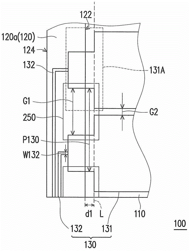
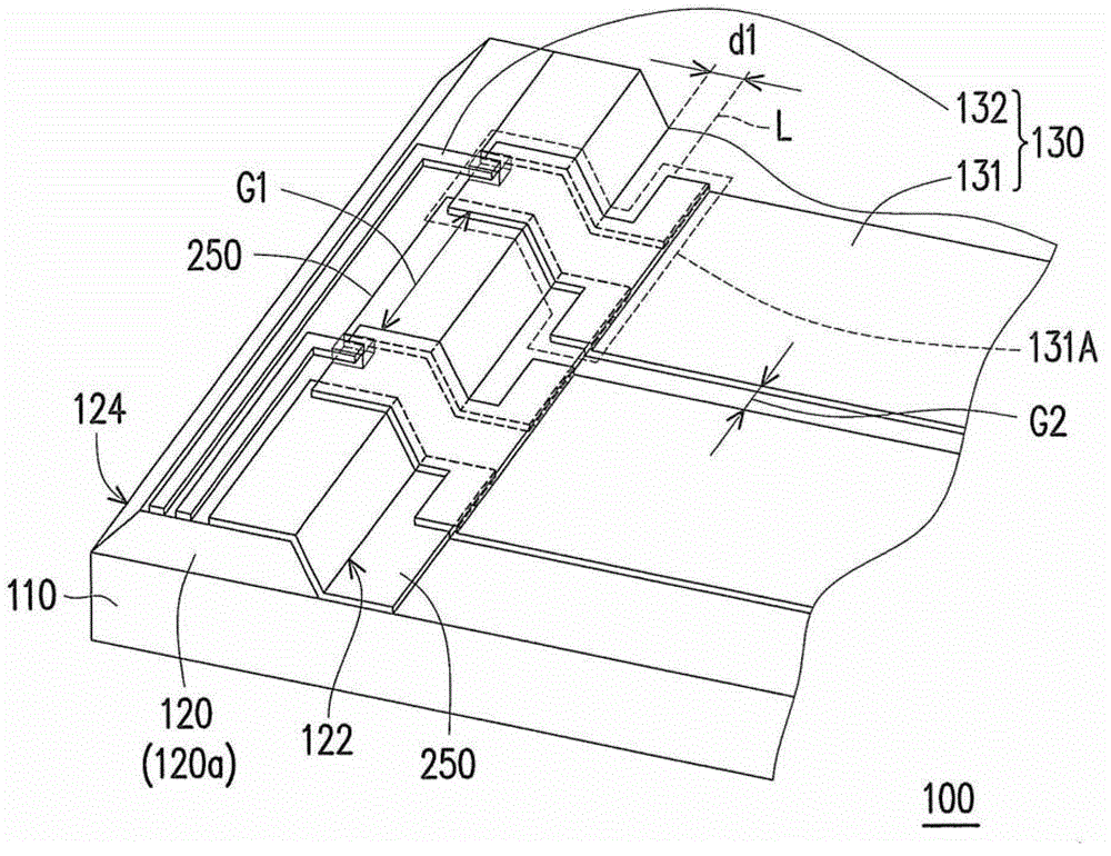
[0060] figure 1 Shown is a partial top view schematic diagram of the touch panel of the first embodiment of the present invention, and figure 2 for figure 1 3D schematic diagram of the touch panel. Please also refer to figure 1 and figure 2 , the touch panel 100 includes a substrate 110 , a decoration layer 120 and a plurality of conductive elements 130 . The substrate 110 can be a rigid transparent substrate, such as a glass substrate, or a flexible transparent substrate, such as a plastic substrate, but not limited thereto. The material of the decoration layer 120 may include at least one of ceramics, diamond-like carbon, ink or organic materials (such as photoresist), but not limited thereto. The plurality of conductive elements 130 are made of conductive materials, which may include transparent conductive materials, such as indium tin oxide (Indium tin oxide, ITO), indium zinc oxide (Indium-Zinc Oxide, IZO), zinc gallium oxide (GZO), nano Carbon Nanotube-based t...


PUM


Abstract

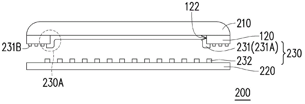
A touch panel including a substrate, a decoration layer, and conductive elements is provided. The decoration layer has an outer margin adjacent to an edge of the substrate and an inner margin opposite to the outer region. A reference line is away from the inner margin with a distance of at least 20 [mu]m towards a direction away from the outer margin. At least one of the conductive elements includes a cross-interface portion which covers the decoration layer and a region of the substrate without the decoration layer. A first distance and a second distance between two adjacent cross-interface portions are provided in a region outward of the reference line to the outer margin of the decoration layer, and in a region inward of the reference line, respectively. The first distance is greater than the second distance. The conductive elements at least construct touch sensing units for forming a capacitance coupling.

Description

technical field [0001] The present invention relates to a touch panel, and in particular to a touch panel provided with a light-resistant layer. Background technique [0002] The input methods of many information products have changed from traditional devices such as keyboards or mice to using touch-sensitive devices as input methods. Therefore, touch panels have been widely used. Generally speaking, in order to transmit the signal generated by the user operating the touch panel, a plurality of wires need to be laid out around the touch panel. In order to prevent the exposed wires from affecting the appearance of the overall device, a decorative layer is usually arranged around the touch panel to cover these wires. [0003] In current manufacturing, although the arrangement of the decoration layer can shield the wires, it forms a raised structure because it covers a part of the surface of the substrate of the touch panel, or, due to the material characteristics of the deco...

Claims


Application Information

Patent Timeline
Patent Type & Authority Applications(China)
IPC IPC(8): G06F3/041
CPCG06F2203/04107G06F3/04164G06F3/0446G06F3/0443
Inventor 林怡君吴明坤黄敬佩陈国兴陈昱廷苏振豪李允斌苏国彰李晏伶
Owner WINTEK CORP
Learn More