
Three-dimensional printer

A technology of a three-dimensional printer and a print head, applied in the field of three-dimensional printers, can solve the problems of reducing response sensitivity, increasing control complexity, and inability to perform fast printing, etc., and achieves the effect of facilitating refueling, simplifying control and the structure of the refueling device

Active Publication Date: 2014-07-30
PRINT RITE UNICORN IMAGE PROD CO LTD
View PDF9 Cites 27 Cited by
  • Summary
  • Abstract
  • Description
  • Claims
  • Application Information

AI Technical Summary

Problems solved by technology

The refueling device is fixedly connected with the print head, and moves with the print head, which makes the print head have a larger mass, reduces its response sensitivity, and cannot perform fast printing; due to the large inertia of the moving part with the print head, the , stop and change direction may easily cause vibration and affect the printing quality; as the number of filament colors increases, the quality of the print head increases accordingly, and the number of motors that the controller needs to control also increases. control complexity

Method used


Image

  • Three-dimensional printer
  • Three-dimensional printer
  • Three-dimensional printer

Examples


no. 1 example

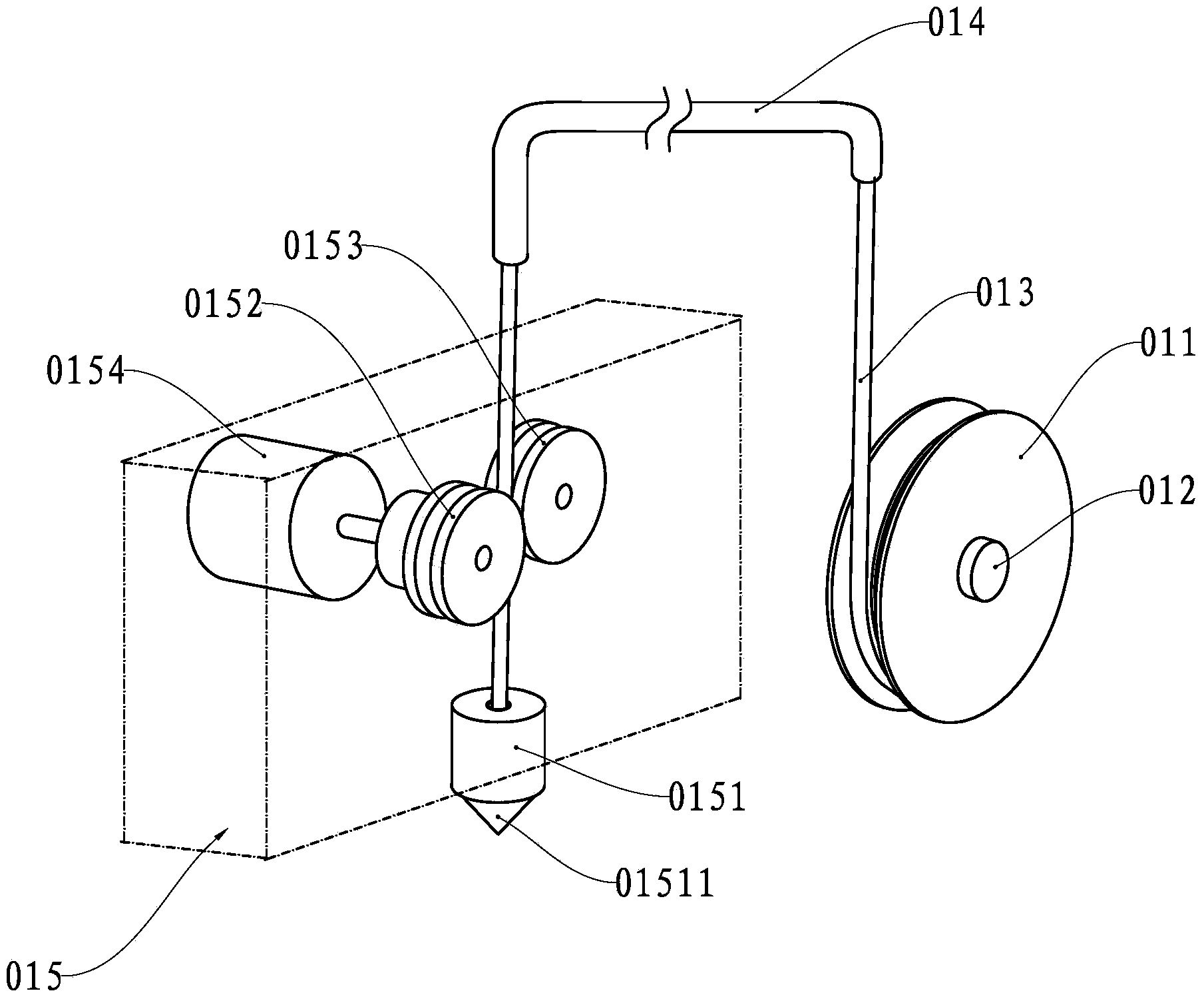
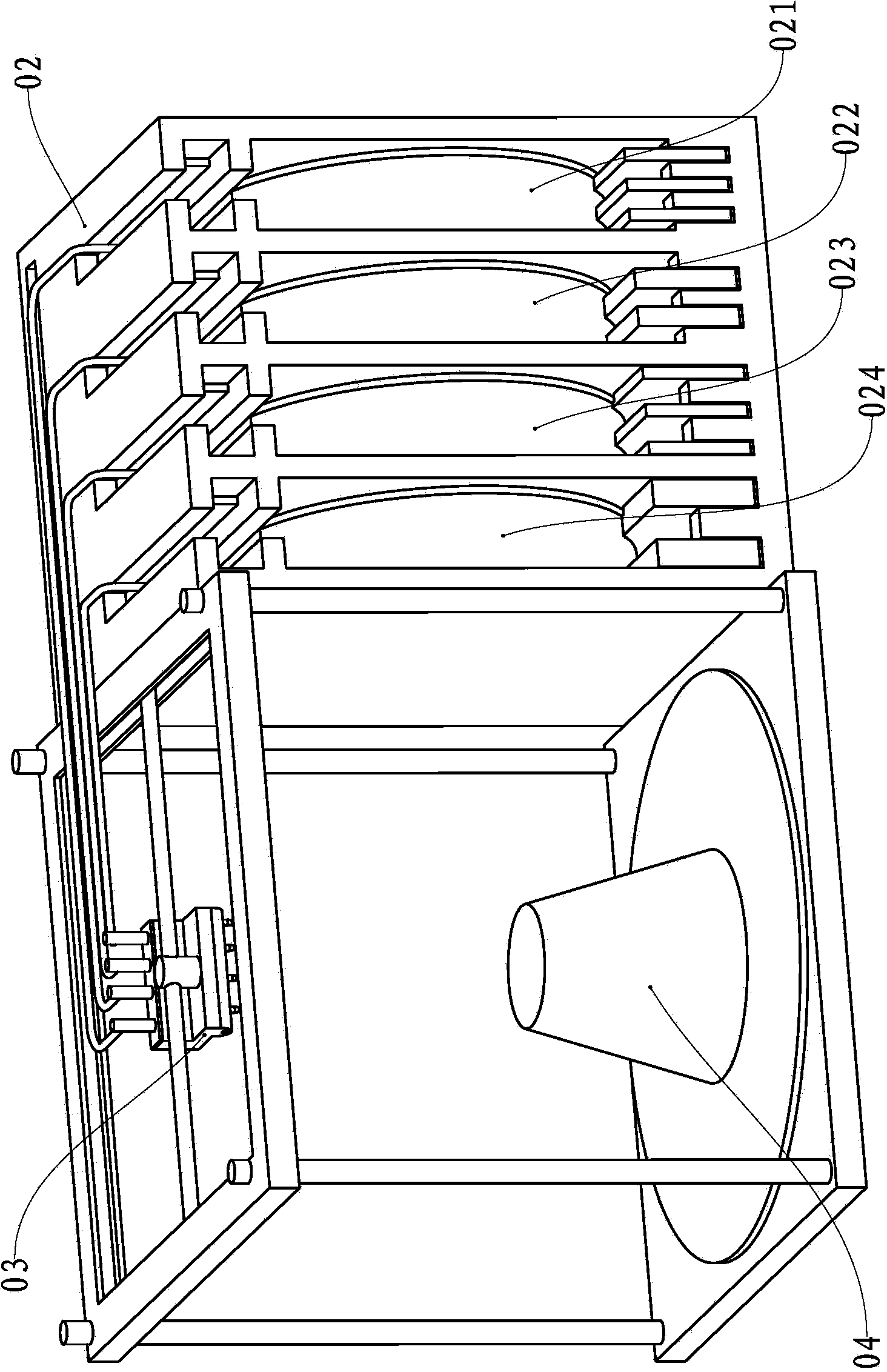
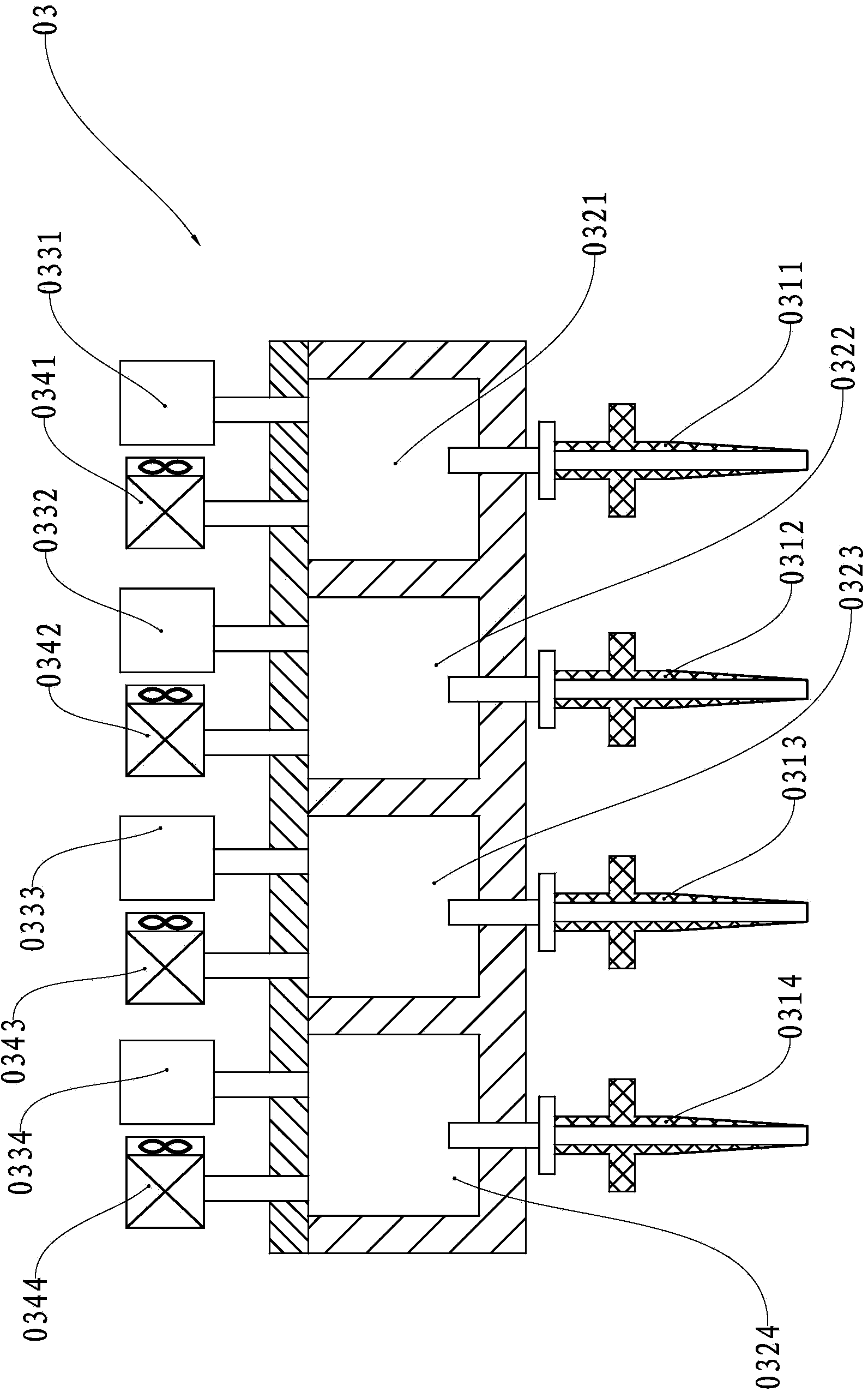
[0033] see Figure 4 , this example three-dimensional printer is made of feeding device 1, refueling device 2, printing head 3, stage 4, frame 5 and controller; The material box 12, the wire material box 13, the wire material box 14, the wire material box 15 and the wire material box 16 are composed; the controller controls the movement of the printing head 3 in the horizontal X-Y plane, and simultaneously controls the stage 4 and the material changer 2 Move in the vertical Z direction; the feeder 2 is a disc body, and the first feeding unit 21, the second feeding unit 22, the third feeding unit 23, and the fourth feeding unit 24 are evenly distributed along the circumference of the feeder 2 , the fifth feeding unit 25 and the sixth feeding unit; the six silk boxes on the feeding device 1 supply monochrome silk to the six feeding units respectively.

[0034] see Figure 5 , the first feeding unit 21 has a feeding wheel 211 and a feeding wheel 212, and the second feeding unit...

no. 2 example

[0046] As an explanation of the second embodiment of the present invention, only the differences from the above-mentioned first embodiment will be described below. The material changer is a rectangular plate structure, and 6 feeding units are installed on the rectangular plate in a line or array.

no. 3 example

[0048] As a description of the third embodiment of the present invention, only the differences from the above-mentioned first embodiment will be described below. The stage and the material changer are fixed relative to the frame, and the print head moves in the X-Y-Z three-dimensional space under the control of the controller; during the material change process, the relative movement between the material changer and the print head is controlled by the controller The print head is complete.


PUM


Abstract

The invention relates to a three-dimensional printer. The three-dimensional printer comprises a rack, a material supply device, a controller, a material replacer and a transmission wheel, wherein a printing head controlled by the controller is movably arranged on the rack, and comprises material supply wheels and a charging hole; the material replacer comprises more than two feeding units; each feeding unit comprises a feeding wheel; a line cutting knife controlled by the controller is arranged beside a discharging hole of each feeding unit; the material supply device supplies silk to the feeding units; the printing head can move in a three-dimensional space relative to the material replacer, so that the charging hole of the printing head is optionally butted with the discharging hole of any feeding unit in a separable manner; when the charging hole of the printing head is butted with the discharging hole of one of the feeding units, the material supply wheels are in transmission connection with the feeding wheels through the transmission wheel. According to the three-dimensional printer, in a printing process, silk can be conveniently replaced, and multi-color printing can be conveniently carried out, so that the trouble of manual material replacement is reduced, and the printing continuity is effectively guaranteed.

Description

technical field [0001] The invention relates to a rapid prototyping device, in particular to a three-dimensional printer. Background technique [0002] A three-dimensional printer is a device based on a digital model that uses materials such as powdered metal or plastic to construct three-dimensional objects by layer-by-layer printing. One of the three-dimensional printers is to supply molding materials to the print head in the form of filaments. The molding materials are heated to a molten state by means of electric heating in the print head. The moving path of the object table is used to print out the three-dimensional object in a layer-by-layer manner. [0003] The background technology of the patent document whose notification number is CN1216726C describes a kind of three-dimensional printer that supplies molding material to the printing head with silk material, see figure 1 , the filament 013 is wound on the filament box 011 and installed on the rotating shaft 012 of...

Claims


Application Information

Patent Timeline
IPC IPC(8): B29C67/00B29C31/08B29C31/10
Inventor 杨燕楠李世强
Owner PRINT RITE UNICORN IMAGE PROD CO LTD
Features
  • Generate Ideas
  • Intellectual Property
  • Life Sciences
  • Materials
  • Tech Scout
  • Unparalleled Data Quality
  • Higher Quality Content
  • 60% Fewer Hallucinations
Learn More