A liquid accumulator for a propellant tank in a space vehicle

A technology for propellant storage tanks and space vehicles, which is applied to space vehicle propulsion system devices, aircraft, space navigation vehicles, etc., can solve the problems of easy pollution, complex structure, low reliability, etc., and achieve a wide range of applications, structural The effect of high strength and simple structure

Active Publication Date: 2016-05-04
BEIJING INST OF CONTROL ENG
View PDF6 Cites 1 Cited by
  • Summary
  • Abstract
  • Description
  • Claims
  • Application Information

AI Technical Summary

Problems solved by technology

The limitations of this type of propellant management device have also gradually emerged, becoming an unfavorable factor restricting the development of the satellite industry
Mesh PMD has the following disadvantages: For example, the capillary mesh structure has low strength, is easy to be damaged, easy to be polluted, and has low reliability. At the same time, complex fluid transmission channels need to be set up, resulting in a large weight of the propellant management device and slow filling speed
For example, a liquid accumulator is described in US4553565A, wherein the storage of liquid and the separation of the gas phase and the liquid phase are realized by means of some radially evenly placed blades. (such as large axial rotational angular velocity of the storage tank, large reverse acceleration or large lateral acceleration, etc.) cannot guarantee sufficient liquid storage without entrainment
Also described in DE10040755A1 is a liquid accumulator similar to a spherical crown. An inner cone-shaped plate is arranged in the liquid accumulator, and some screen collectors and several guides are arranged in appropriate areas according to the requirements of on-orbit working conditions. The disadvantages of the flow vane are: the structure is more complex, more screens are used, and the liquid storage capacity is small
Also described a kind of accumulator in US4986398A, wherein realizes liquid storage by means of conical structure area, its shortcoming is: used a large amount of screen meshes, and a large amount of air bubbles are easy to accumulate on the screen in the accumulator; The accumulator provides The liquid flow rate of the liquid is small, and the flow rate is too large to easily cause the flow in the accumulator to stop, and it is easier to accelerate the accumulation of air bubbles on the sieve in the accumulator, and in the worse case, the gas is forced to pass through the sieve; at the same time, in the case of microgravity The accumulator is still difficult to fill and retain enough liquid driven by surface tension

Method used


Image

  • A liquid accumulator for a propellant tank in a space vehicle
  • A liquid accumulator for a propellant tank in a space vehicle
  • A liquid accumulator for a propellant tank in a space vehicle

Examples


Embodiment Construction

[0036] Below in conjunction with accompanying drawing and specific embodiment the present invention is described in further detail:

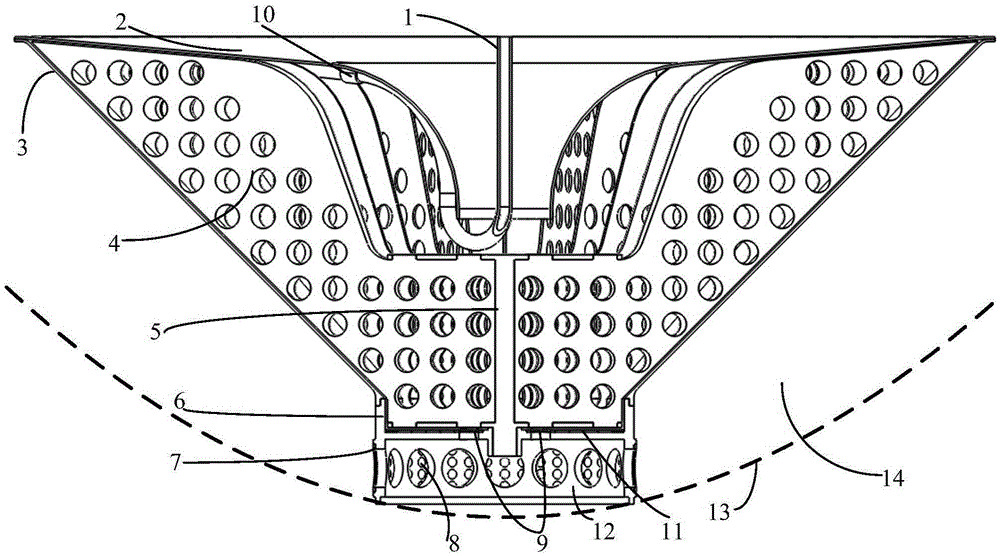
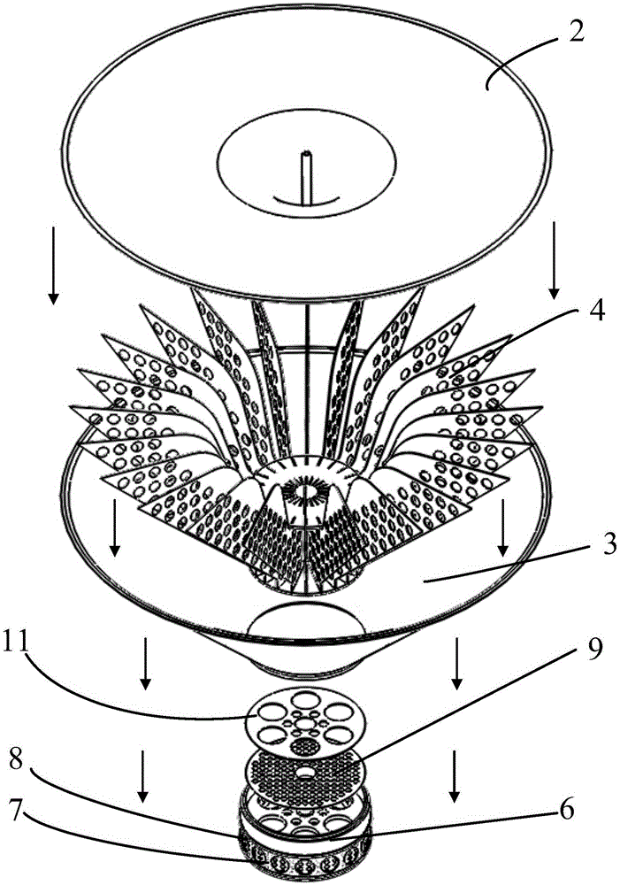
[0037] Such as figure 1 , 2 As shown, the present invention provides a liquid accumulator for a propellant storage tank in a space vehicle, comprising an air duct 1, a cover plate 2, a casing 3, a blade 4, a pillar 5, a base 6, a passage window pressure plate 7, a passage The window mesh 8, the liquid accumulator mesh 9, the fixed block 10 and the liquid accumulator mesh pressing plate 11; the channel window mesh 8 and the liquid accumulator mesh 9 are made of titanium alloy.

[0038] Such as Figure 6 As shown, the pillar 5 includes a center column 51, an upper support plate 52 and a lower support plate 53; the upper support plate 52 and the lower support plate 53 are coaxially connected by the center column 51, the upper support plate 52 is located at the top of the center column 51, and the lower support plate 52 is located at the top of th...


PUM


Abstract

A liquid storage device for a propellant tank in a spacecraft includes a gas-guide tube, a cover plate, a housing, blades, a supporting column, a base, a passage-window pressing plate, a passage-window mesh piece, a liquid-storage-device mesh piece, a fixing block, and a pressing plate for the liquid-storage-device mesh piece. The blades are uniformly distributed on and fixed to the support column in a radial direction to form an integral structure, and the integral structure is mounted on and fixed to a circular partition plate in the base. The liquid-storage-device mesh piece is pressed on the circular partition plate in the base by the pressing plate for the liquid-storage-device mesh piece and then is fixed. The passage-window mesh piece is pressed on the outer side of a cylinder wall of the base by the passage-window pressing plate and then is fixed.

Description

technical field [0001] The invention relates to a liquid accumulator for space fluid management, especially suitable for propellant storage tanks in space vehicles. Background technique [0002] Propellant tanks are widely used in various space vehicles such as satellites, spaceships, space stations, and launch vehicles due to their high reliability and long life in a weightless environment. The core technology of the propellant tank is its internal propellant management device (referred to as PMD). The ability to manage PMD is a key indicator of tank performance. The goal of the PMD design is for the PMD to deliver liquids reliably and without air bubbles at all times. [0003] At present, the PMDs of the propellant storage tanks used in space vehicles, especially satellites, are all mesh-type, and the screen is used as a capillary element to collect the propellant, and the propellant is transported to the liquid port of the propellant storage tank by the pipeline. . Th...

Claims


Application Information

Patent Timeline
Patent Type & Authority Patents(China)
IPC IPC(8): B64G1/40F17C1/00
CPCB64G1/402F17C13/008F17C2270/0194F02K9/605
Inventor 胡齐李永潘海林陈健魏延明庄保堂刘锦涛
Owner BEIJING INST OF CONTROL ENG
Why Eureka
Try Eureka