Electronic lock capable of detecting rotating direction of lock cylinder and working method for electronic lock

A technology of rotation direction and working method, which is applied in the field of locks, can solve the problems of affecting the accuracy of judgment results, being easily disturbed by the external environment, and complicated implementation methods, and achieves the effects of flexible and diverse implementation methods, strong aesthetics, and easy implementation

Active Publication Date: 2014-07-30
ZHUHAI UNITECH POWER TECH CO LTD
View PDF5 Cites 9 Cited by
  • Summary
  • Abstract
  • Description
  • Claims
  • Application Information

AI Technical Summary

Problems solved by technology

[0005] However, this implementation method is more complicated, and it can only be realized by precise calculation through the evaluation circuit; and the sensor is a precision electronic component, which is easily disturbed by the external environment, which may affect the accuracy of the judgment result; and for those who do not have For locks that turn the handle or directly use the key to open the lock, it is impossible to judge this situation
[0006] Therefore, there is currently no suitable structure or method for detecting and judging whether the electronic lock is in the unlocked or locked state, and there are still many problems in the electronic lock when judging whether the lock cylinder is in the unlocked or locked state.

Method used


Image

  • Electronic lock capable of detecting rotating direction of lock cylinder and working method for electronic lock
  • Electronic lock capable of detecting rotating direction of lock cylinder and working method for electronic lock
  • Electronic lock capable of detecting rotating direction of lock cylinder and working method for electronic lock

Examples


Embodiment Construction

[0050] The present invention is described in detail through the following embodiments. However, those skilled in the art should understand that the following embodiments do not limit the protection scope of the present invention, and any improvements and changes made on the basis of the present invention are within the protection scope of the present invention.

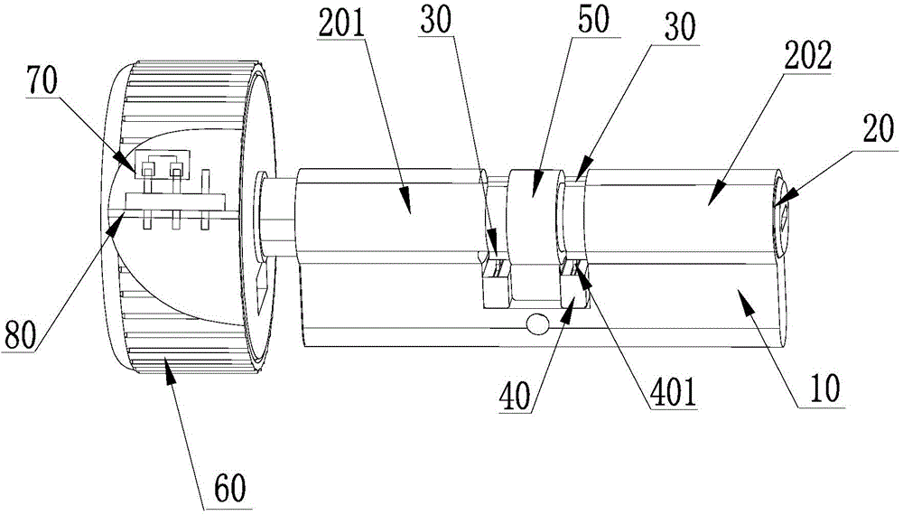
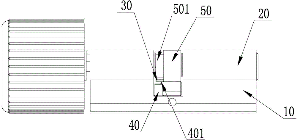
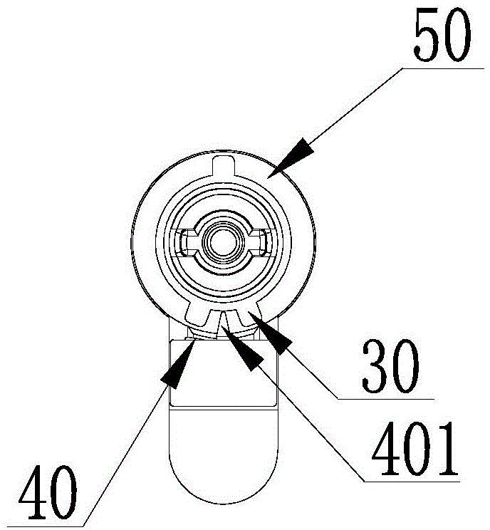
[0051] The present invention proposes an electronic lock capable of detecting the rotation direction of the lock core, which is mainly composed of a lock body 10 and a lock core 20, wherein at least one convex key 30 is fixed on the rotating shaft of the lock core 20; At least one position sensor 40 is installed at the corresponding position of the convex key 30, and, on the lock body 10, close to the position sensor 40, a rocker 401 is installed in the direction of the rotation axis of the lock cylinder 20, which rotates on the rotation axis of the lock cylinder 20 When pushed by the convex key 30, it can swing to bo...


PUM


Abstract

The invention discloses an electronic lock capable of detecting the rotating direction of a lock cylinder and a working method for the electronic lock. The electronic lock mainly comprises a lock body and the lock cylinder, wherein a rotating shaft of the lock cylinder is fixedly provided with at least one convex key; at least one position sensor is arranged at a position, corresponding to the convex key, of the lock body; a rocker arm is arranged close to the position sensor on the lock body, and points to the direction of the rotating shaft of the lock cylinder, and the rocker arm is pushed by the convex key when the rotating shaft of the lock cylinder is rotated so as to swing to two sides and trigger the position sensor. According to the electronic lock disclosed by the invention, the rotating direction of the lock cylinder is detected by matching the convex key, the position sensor and the rocker arm, the unlocking or locking state of the lock cylinder is judged based on the structure, and the electronic lock has the advantages of simple structure, low cost, flexible implementation method, high reliability and the like.

Description

technical field [0001] The invention relates to the field of locks, in particular to an electronic lock and a working method thereof. Background technique [0002] Lockset is a common safety protection device in people's daily life, mainly composed of lock body, lock cylinder and other components. Among them, the lock cylinder is installed inside the lock body, which is divided into two parts: the inner lock cylinder for indoor unlocking operation and the outer lock cylinder for outdoor unlocking operation. Both the inner lock cylinder and the outer lock cylinder can be moved by rotating the lock cylinder. The latch of the lock body moves, so that the unlocking and locking of the lockset can be realized. The unlocked or locked state of the lock can provide corresponding processing basis for smart home or security system. [0003] In the existing intelligent electronic locks, the lock cylinder is usually only used as a simple control mechanism, which only realizes the unloc...

Claims


Application Information

Patent Timeline
Patent Type & Authority Applications(China)
IPC IPC(8): E05B17/22E05B47/06
Inventor 高永昊卢武将任冲徐亮
Owner ZHUHAI UNITECH POWER TECH CO LTD
Why Eureka
Try Eureka