Parallel-type oil-gas separator for crankcase ventilation

A technology of oil-gas separator and crankcase ventilation, which is applied in the direction of crankcase ventilation, machine/engine, engine components, etc. It can solve the problems of complex structure, high cost, and engine space occupation, so as to achieve flexible space layout, improve emission performance, The effect of high-efficiency oil and gas separation

Inactive Publication Date: 2014-07-30
QINGDAO XINTIECHENG AUTO PARTS
View PDF0 Cites 8 Cited by
  • Summary
  • Abstract
  • Description
  • Claims
  • Application Information

AI Technical Summary

Problems solved by technology

This method needs to add additional structural or functional components to realize, usually the cost is high, the structure is more complicated, and it needs to occupy a certain amount of engine space

Method used


Image

  • Parallel-type oil-gas separator for crankcase ventilation
  • Parallel-type oil-gas separator for crankcase ventilation
  • Parallel-type oil-gas separator for crankcase ventilation

Examples


Embodiment Construction

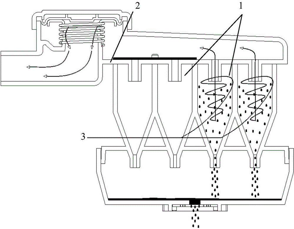
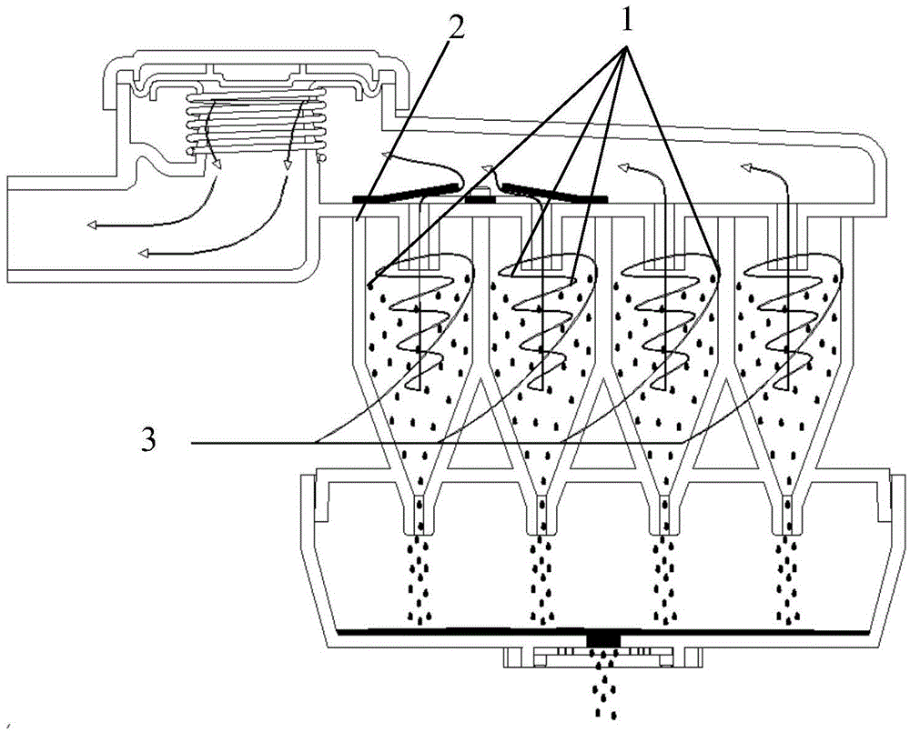
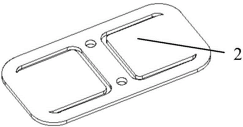
[0016] The side-by-side oil-gas separator for crankcase ventilation of the present invention is composed of a vibration valve and 4 side-by-side swirl chambers, a vibration valve is arranged above the 2 whirl chambers, and the vibration valve is arranged above the two whirl chambers , The vibrating valve is a sheet-like structure of spring steel material, with an opening on it, which can be opened or closed under the action of external force. The vibrating valve is assembled above the swirl chamber by riveting or clipping.

[0017] When the engine is working, the pressure in the crankcase is greater than the pressure in the intake manifold. With the different operating conditions of the engine, the amount of crankcase blow-by gas 3 changes, so the pressure difference between the crankcase and the intake manifold also changes accordingly. In the case of low blow-by gas in the crankcase, the pressure difference between the crankcase and the intake manifold is small, and the pres...


PUM


Abstract

The invention relates to a parallel-type oil-gas separator for crankcase ventilation. The parallel-type oil-gas separator for crankcase ventilation consists of a vibrating valve and a plurality of cyclone chambers, wherein the vibrating valve is arranged above at least one cyclone chamber, the vibrating valve is arranged above two cyclone chambers, the vibrating valve is of a sheet structure made of a spring steel material and is provided with an opening, the opening or the closing of the opening can be realized under the effect of external force and the vibrating valve is assembled above the cyclone chambers in a riveting or clamping way. By using the spring steel vibrating valve, the vibrating valve is enabled to have a good elastic deformation capacity and high fatigue strength and can be used under conditions of impact, vibration or long-term alternating stress. Since the plurality of cyclone chambers are arranged in parallel, the pressure loss is effectively reduced and the oil-gas separation efficiency during gas blow-by of a crankcase is improved. Since the vibrating valve and the plurality of cyclone chambers are jointly applied, the number of opened cyclone chambers can be controlled according to the blow-by amount of the crankcase of an engine under different working conditions, the oil-gas separation efficiency of the engine under different working conditions is improved and the exhaust performance of the engine is effectively improved.

Description

technical field [0001] The invention relates to the technical field of engines, in particular to an engine cylinder head cover integrated with an oil-air separation function and an oil-air separator for a crankcase ventilation system. Background technique [0002] When the engine is working, due to the gap between the cylinder wall, piston and piston ring, a part of the mixed gas (including fuel, oil, water vapor and other vapors) enters the crankcase. The environmental protection law requires that the pressure in the crankcase should be negative pressure, so the existing Most engines use a forced crankcase ventilation system. During the working process of the engine, the negative pressure of the intake manifold is used to suck the oil and gas in the crankcase into the cylinder head cover or the oil and gas separator, and the oil and gas are separated through a series of oil and gas separation structures. After the gas with low density is separated, it is sucked into the in...

Claims


Application Information

Patent Timeline
Patent Type & Authority Applications(China)
IPC IPC(8): F01M13/04
Inventor 王强
Owner QINGDAO XINTIECHENG AUTO PARTS
Why Eureka
Try Eureka