Dry type particle granularity measuring method

A measurement method and particle technology, which is applied in the direction of measurement devices, particle size analysis, particle and sedimentation analysis, etc., can solve the problems of long measurement time, cumbersome operation, and low measurement accuracy, and achieve the effect of avoiding cumbersome measurement process and improving measurement accuracy

Inactive Publication Date: 2014-07-30
HEBEI UNIVERSITY
View PDF10 Cites 6 Cited by
  • Summary
  • Abstract
  • Description
  • Claims
  • Application Information

AI Technical Summary

Problems solved by technology

[0006] The purpose of the present invention is to provide a dry particle size measurement method to solve the problems of cumbersome operation, long measurement time and low measurement accuracy caused by particle circulation in the existing dry and wet measurement technologies

Method used


Image

  • Dry type particle granularity measuring method
  • Dry type particle granularity measuring method
  • Dry type particle granularity measuring method

Examples


Embodiment 1

[0039] The specific process of the dry particle size measurement method in the present embodiment is as follows:

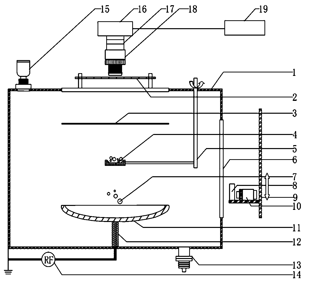
[0040] Step a: Reference figure 1 , first set a vacuum chamber 1, the vacuum chamber 1 is surrounded by a stainless steel cavity, and the stainless steel cavity is grounded; in the vacuum chamber 1, the upper and lower plates are horizontally arranged, the upper plate 3 is grounded, and the lower plate 11 is connected to the radio frequency The power electrode of the power supply 14 and the other electrode of the radio frequency power supply 14 are grounded, and the radio frequency power supply 14 is placed outside the vacuum chamber 1 . When the RF power supply 14 is turned on, the lower plate 11 is negatively charged (or has a negative potential), and uniform plasma can be generated between the upper and lower plates through gas discharge.

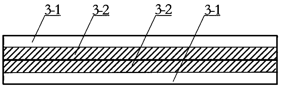
[0041] Such as figure 2 As shown, the upper plate 3 is made up of two pieces of ITO conductive glass, and each piece of...

Embodiment 2

[0065] Compared with embodiment 1, this embodiment has the following differences:

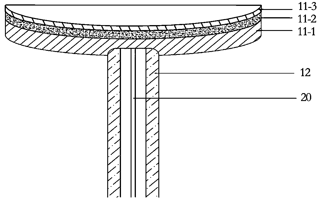
[0066] The power supply in step a of this embodiment is a DC power supply, the lower pole plate is connected to the negative pole of the DC power supply, the positive pole of the DC power supply is grounded, and the DC power supply is placed outside the vacuum chamber; Prevent the particles scattered from the particle pool from falling to the glass ring outside the lower plate. A preferred embodiment is: a frosted layer is formed on the surface of the metal plate through a frosting process, and a blackened layer is formed on the surface of the frosted layer through a blackening process.

[0067] Step d is: turn on the DC power supply, adjust the voltage of the DC power supply to 350V, make the lower plate have a negative potential, and generate uniform plasma between the upper and lower plates through gas discharge under the action of the DC power supply.

[0068] Step f is: turn on the light so...


PUM

PropertyMeasurementUnit
Center wavelengthaaaaaaaaaa

Abstract

The invention provides a dry type particle granularity measuring method. The measuring method comprises the following steps: providing a vacuum chamber, and arranging an upper pole plate, a lower pole plate and a particle pond in the vacuum chamber; switching on a power supply, and generating uniform plasmas between the upper pole plate and lower pole plate in the vacuum chamber; scattering particles to be measured out of the particle pond, forming a dispersed suspended particle system in the plasmas in the vacuum chamber by using the scattered particles; irradiating the suspended particles by adopting laser light, and scattering; recording a Brownian motion trace image by using a camera above the vacuum chamber; calculating the sizes of the particles according to the Brownian motion principle of the particles through a computer to obtain the granularity distribution pattern of the particles. The method is easy and convenient to operate, and rapid and accurate in measurement, and a solution is provided for the rapid analysis and detection in laboratories and the industrial field.

Description

technical field [0001] The invention relates to a particle size measurement method, in particular to a dry particle size measurement method. Background technique [0002] Particle size analyzer is an instrument used to test the size and distribution of solid particles. It has been widely used in the fields of biology, physics, chemical industry, pharmaceuticals and environmental pollution analysis. Existing particle size analyzers include laser particle size analyzers and particle imagers. The laser particle size analyzer adopts the principle of Mie scattering to test the dynamic particles. The dynamic particles can be dispersed by wet method, dry method or integrated method of dry and wet. [0003] The existing laser particle size analyzer basically consists of four main parts: 1) light source system; 2) suspension system; 3) detection system; 4) computer processing system. Most of the light sources in the light source system use monochromatic and directional lasers, and ...

Claims


Application Information

Patent Timeline
IPC IPC(8): G01N15/02
Inventor 贺亚峰宫卫华冯帆张永亮董丽芳
Owner HEBEI UNIVERSITY
Why Eureka
Try Eureka