A dry microparticle separation method

A technology of tiny particles and separation methods, applied in solid separation, electrostatic effect separation, chemical instruments and methods, etc., can solve the problems of long processing time, low separation precision, cumbersome operation of dry and wet separation techniques, and achieve operational simple effect

Active Publication Date: 2017-08-01
HEBEI UNIVERSITY
View PDF6 Cites 0 Cited by
  • Summary
  • Abstract
  • Description
  • Claims
  • Application Information

AI Technical Summary

Problems solved by technology

[0004] The purpose of the present invention is to provide a dry micro particle separation method to solve the problems of cumbersome operation, long processing time and low separation precision in the existing dry and wet separation technologies

Method used


Image

  • A dry microparticle separation method
  • A dry microparticle separation method

Examples


Embodiment Construction

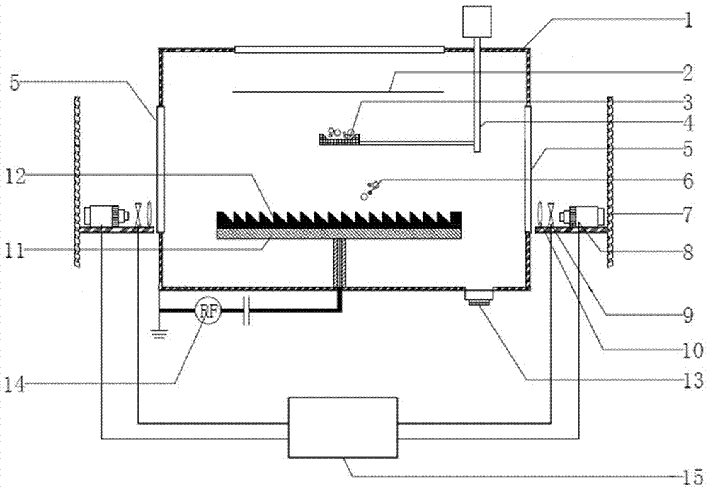
[0030] The dry microparticle separation method provided by the present invention relies on a dry microparticle separation device, such as figure 1 As shown, the dry micro particle separation device includes a vacuum chamber 1, the vacuum chamber 1 is surrounded by a stainless steel cavity, and the stainless steel cavity is grounded; in the vacuum chamber 1, two upper and lower plates are horizontally arranged, which are respectively the upper plate 2 And lower plate 11. In this embodiment, the upper pole plate 2 is composed of two pieces of ITO conductive glass stacked together, and the lower pole plate 11 is a flat metal plate. The upper plate 2 is grounded, the lower plate 11 is connected to the power electrode of the radio frequency power supply 14 , and the other electrode of the radio frequency power supply 14 is grounded. The radio frequency power supply 14 is located outside the vacuum chamber 1 . When the lower plate 11 is connected to the power electrode of the radio...


PUM

PropertyMeasurementUnit
Center wavelengthaaaaaaaaaa
Curvatureaaaaaaaaaa

Abstract

The invention provides a dry fine particle separation method. An upper polar plate, a lower polar plate, a particle pool and a particle separator are arranged in a vacuum chamber; a radio frequency power supply, a semiconductor laser, a chopper and a beam expander are arranged out of the vacuum chamber; and the radio frequency power supply is communicated to generate uniform plasma between the upper and lower polar plates. The particle separator is positioned on the lower polar plate, and includes a ratchet curved surface groove in the middle part and collecting boxes at two ends; particles scattered from the particle pool can be located in a suspension state in the ratchet curved surface groove; and the power of the semiconductor laser and the frequency of the chopper are adjusted, so that the laser irradiates the particles to push the particles to form oscillation with a specific frequency, and the particles with different sizes move in the ratchet curved surface groove in opposite directions to finish separation. The dry fine particle separation method can realize separation of fine particles with lower content. The dry fine particle separation method is simple and convenient for operation, and provides a solution for quick separation in laboratories and industrial field.

Description

technical field [0001] The invention relates to a particle separation method, in particular to a dry micro particle separation method. Background technique [0002] The separation of one or several microparticles is a very meaningful work, and has great application prospects in sample storage, physical property analysis of particles, biochemical analysis, and further formation of functional integrated chips. The current separation methods are divided into dry method and wet method. Wet separation includes the method of separating particles in microflow. The more effective physical methods are usually electrophoresis technology using uniform electric field, dielectrophoresis technology based on inhomogeneous electric field, magnetophoresis technology based on inhomogeneous magnetic field, and acoustophoresis technology based on sound waves . In these methods, particles of different sizes flow to different channels under the action of force, so that spatial separation can be...

Claims


Application Information

Patent Timeline
IPC IPC(8): B03C7/04
CPCB03C7/04B03C2201/10
Inventor 贺亚峰冯帆闫佳刘富成范伟丽董丽芳
Owner HEBEI UNIVERSITY
Why Eureka
Try Eureka