MOS grid-control thyristor

A thyristor and gate control technology, applied in thyristors, electrical components, circuits, etc., can solve the problems of lack of current saturation characteristics, weak turn-off capability, complicated manufacturing process, etc., to reduce turn-off time, reduce turn-off loss, and better The effect of the turn-off loss trade-off

Inactive Publication Date: 2014-07-30
UNIV OF ELECTRONICS SCI & TECH OF CHINA
View PDF4 Cites 9 Cited by
  • Summary
  • Abstract
  • Description
  • Claims
  • Application Information

AI Technical Summary

Problems solved by technology

[0004] What the present invention aims to solve is to solve the above-mentioned disadvantages of lack of current saturation characteristics and weak turn-off ability in the traditional MCT, and the existing new structure has the problem of complicated manufacturing processes, and proposes a JFET-controlled MOS gate-controlled thyristor (JFET -MCT)

Method used


Image

  • MOS grid-control thyristor
  • MOS grid-control thyristor
  • MOS grid-control thyristor

Examples


Embodiment Construction

[0019] Below in conjunction with accompanying drawing, describe technical scheme of the present invention in detail:

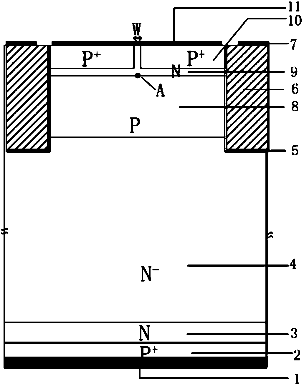
[0020] like image 3 As shown, a MOS gate-controlled thyristor of the present invention has a cell structure including an anode P region 2, a metallized anode 1 arranged on the lower end surface of the anode P region 2, and an N-type buffer layer arranged on the upper end surface of the anode P region 2 3 and the N disposed on the upper end face of the N-type buffer layer 3 - Drift region 4; the N - The upper layer of the drift region 4 is provided with a P well 8, an N well 9 and an insulating gate, wherein the P well 8 and the N well 9 are located in the middle, and the two sides are insulating gates; The gate oxide layer 5 is composed of a metallized gate 7 on the upper surface of the polysilicon gate; the N well 9 is located on the upper end surface of the P well 8; the N well 9 includes two independent P + Cathode contact area 10, two P + The cathode ...


PUM


Abstract

The invention relates to the semiconductor technology, in particular to an MOS grid-control thyristor. A P+ cathode contact area 10 is modified, the width of the P+ cathode contact area 10 is increased, the metallurgical junction form is changed, and the conveying passage of electrons flowing from cathode metal 11 is shortened. The forward direction work characteristic of a device is controlled by a JFET composed of the P+ cathode contact area 10 and an N-trap 9, a channel pinch-off effect can occur under a relatively small anode voltage, the intensity of saturation current of the device can be controlled, and optimization valuing can be carried on the junction depth and width of the P+ cathode contact area 10 according to the design requirements of the device. The MOS grid-control thyristor is particularly suitable for the MOS grid-control thyristor.

Description

technical field [0001] The invention relates to semiconductor technology, specifically designing a MOS gate-controlled thyristor. Background technique [0002] Thyristor is the abbreviation of thyristor, and it was also referred to as thyristor in the past. Shortly after the application of power diodes, Bell Laboratories in the United States invented the thyristor. In 1957, General Electric Company of the United States developed the world's first thyristor product, which was commercialized in 1958. Since the 1980s, researchers have tried to replace it with insulated gate bipolar transistors (IGBTs). However, thyristors still play an important role in large-capacity applications such as high voltage and high current. This is precisely due to the internal working principle of the thyristor: when working in the forward direction, the PNP and NPN transistors form a positive feedback, the anode has hole injection, and the cathode side also has electron injection, and the conduct...

Claims


Application Information

Patent Timeline
Patent Type & Authority Applications(China)
IPC IPC(8): H01L29/74H01L29/423H01L29/10
CPCH01L29/0839H01L29/42308H01L29/7455H01L29/749
Inventor 陈万军肖琨程武杨骋王珣阳张波
Owner UNIV OF ELECTRONICS SCI & TECH OF CHINA
Why Eureka
Try Eureka