Voltage conversion circuit and control method

A voltage conversion circuit and conversion technology, applied in the direction of high-efficiency power electronic conversion, output power conversion devices, electrical components, etc., can solve problems such as high power and consumption, and achieve the effect of improving transient response performance

Active Publication Date: 2014-07-30
CHENGDU MONOLITHIC POWER SYST
View PDF7 Cites 16 Cited by
  • Summary
  • Abstract
  • Description
  • Claims
  • Application Information

AI Technical Summary

Problems solved by technology

This characteristic poses a great risk when the conversion circuit 10 operates in a noisy environment
Second, in order to adapt to the ramp signal with a smaller amplitude, other circuit units such as comparators have to consume more power to achieve the required speed

Method used


Image

  • Voltage conversion circuit and control method
  • Voltage conversion circuit and control method
  • Voltage conversion circuit and control method

Examples


Embodiment Construction

[0020] Specific embodiments of the present invention will be described in detail below, and it should be noted that the embodiments described here are only for illustration, not for limiting the present invention. In the following description, numerous specific details are set forth in order to provide a thorough understanding of the present invention. It will be apparent, however, to one of ordinary skill in the art that these specific details need not be employed to practice the present invention. In other instances, well-known circuits, materials or methods have not been described in detail in order to avoid obscuring the present invention.

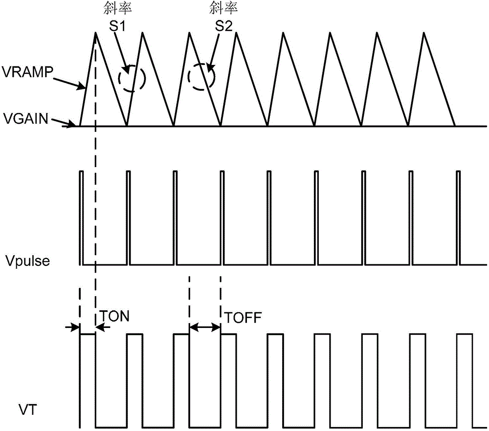
[0021] Here and below, "conduction time" refers to the duration of conduction of the main switch (such as the high-side switch in some embodiments) in each working cycle in a conversion circuit. "OFF time" means the duration during which the main switch is turned off in each duty cycle.

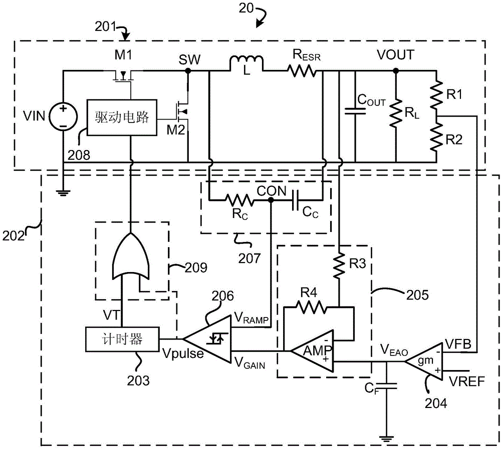
[0022] figure 2 A schematic circuit diagram...


PUM


Abstract

The application relates to a voltage conversion circuit and a control method. The voltage conversion circuit comprises an error amplifier which generates an error signal; a ratio amplification circuit which generates a gain signal according to output voltage and the error signal; a first comparator which generates a pulse signal according to the gain signal and a comparison signal; and a timer which generates a timing signal according to the pulse signal for indicating the turning-on / off time of the voltage conversion circuit. At least one of the gain signal and the comparison signal comprises a slope component, and the turning-on time of the voltage conversion circuit is constant. The technical scheme of the application can effectively improve the transient-state response performance of the voltage conversion circuit.

Description

technical field [0001] The present invention relates to the field of power circuits, specifically but not limited to a voltage conversion circuit and a control method. Background technique [0002] Switching power supplies are widely used in modern electronic products. Traditional switching power supplies mostly use pulse width modulation (PWM) control mode to adjust the output of the power supply. Such a mode usually makes the circuit structure complex, the transient response is slow, and therefore, the performance is not good in high current applications. [0003] Compared with PWM control mode, pulse width modulation control mode (PFM) mainly includes constant on-time control mode, constant off-time control mode and hysteresis control mode, etc. Advantage. figure 1 A constant on-time voltage conversion circuit 10 in the prior art is shown. The voltage conversion circuit 10 mainly includes a DC-DC (DC-DC) step-down converter 101 and a controller 102 . In the controlle...

Claims


Application Information

Patent Timeline
Patent Type & Authority Applications(China)
IPC IPC(8): H02M3/10H02M1/00
CPCH02M3/1588H02M1/0003Y02B70/10H02M3/156
Inventor 杨波席小玉
Owner CHENGDU MONOLITHIC POWER SYST
Why Eureka
Try Eureka