Low-voltage-difference linear voltage regulator system

A low-dropout linear and voltage regulator technology, applied in the electrical field, can solve the problems of weakening product endurance, low conversion efficiency of LDO circuits, and limited use.

Pending Publication Date: 2019-05-03
麦堆微电子技术(上海)有限公司
View PDF0 Cites 6 Cited by
  • Summary
  • Abstract
  • Description
  • Claims
  • Application Information

AI Technical Summary

Problems solved by technology

Although the on-chip Capless LDO avoids the use of extra pins, because the capacitance of the on-chip capacitor (picofarad level) is much smaller than the off-chip capacitor, its transient response cannot meet the requirements of high-speed circuits when applied to high-speed changing loads. Even if some designs ensure that the LDO has good transient performance by increasing the static power consumption of the LDO, the large power consumption consumes the battery energy too quickly, which greatly reduces the battery life.
The disadvantages of ordinary Capless LDOs largely limit the use of on-chip LDOs
In addition, the current trend of intelligent and portable electronic equipment makes electronic products almost completely dependent on chemical batteries such as lithium batteries for power supply. LDO is used as a power management circuit, and its high conversion efficiency can effectively prolong the service life of the battery. In the current study, the conversion efficiency of the LDO circuit is low

Method used


Image

  • Low-voltage-difference linear voltage regulator system
  • Low-voltage-difference linear voltage regulator system
  • Low-voltage-difference linear voltage regulator system

Examples


Embodiment Construction

[0060] The low dropout linear voltage regulator system of the present invention will be further described in detail below in conjunction with the accompanying drawings.

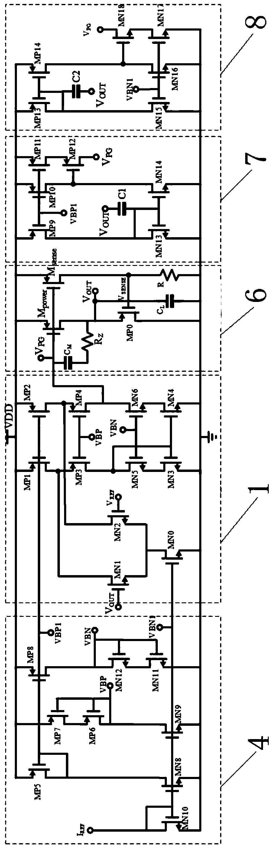
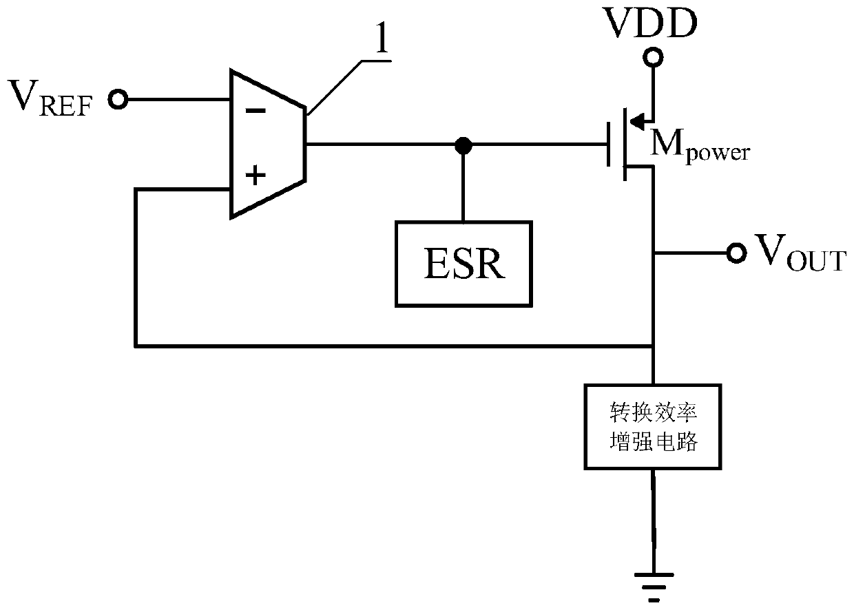
[0061] Such as figure 1 , figure 2 As shown, the system consists of error amplifier 1, slew rate enhancement circuit (ESR circuit), conversion efficiency enhancement circuit, power tube M power composition. V REF It is the reference voltage provided by other modules, often provided by the bandgap reference circuit, VDD is the input power supply voltage signal, which can be provided by the battery or the voltage signal generated after the DC-DC conversion circuit, V OUT It is the output signal of LDO, which is used to provide power supply voltage signal to other circuits.

[0062] Specific examples of this design figure 2 shown, but not limited to figure 2 form. figure 2 The embodiment is composed of a module bias circuit 4 , an error amplifier 1 , an output power tube and a current efficiency enhan...


PUM


Abstract

Provided in the invention is a low-voltage-difference linear voltage regulator system comprising an error amplifier, a power tube, a conversion efficiency enhancement circuit, and a slew rate enhancement circuit. An inverted input terminal of the error amplifier is connected with a reference voltage VREF; and a non-inverted input terminal of the error amplifier is connected with an output voltageVOUT of an LDO. A grid terminal of the power tube is connected with the output terminal of the error amplifier; a source terminal of the power tube is connected with a power supply voltage VDD; and adrain terminal of the power tube is connected with an output voltage VOUT of the LDO. One end of the conversion efficiency enhancement circuit is connected with the non-inverted input terminal of theerror amplifier and the drain terminal of the power tube and the other end of the conversion efficiency enhancement circuit is grounded. The output terminal of the slew rate enhancement circuit is connected with the drain terminal of the power tube. According to the invention, in order to eliminate the restriction of the Capless LDO on a common chip, the system uses the slew rate enhancement circuit to improve the transient response of the LDO and employs the conversion efficiency enhancement circuit to realize high conversion efficiency, thereby prolonging the service life of the power supplydevice.

Description

technical field [0001] The invention relates to the field of electricity, in particular to a power management circuit, in particular to a low-dropout linear regulator system. Background technique [0002] In the prior art, the low dropout linear regulator system includes two types with off-chip load capacitors and on-chip Capless. The former can effectively improve the transient performance of the circuit through off-chip large capacitors (microfarads), but requires additional Pins, on the one hand, increase the difficulty of packaging, and on the other hand, increase the production cost. The latter are all integrated on the chip and are suitable for SOC systems, which can avoid adding extra pins, reduce the difficulty of packaging, and save production costs. Although the on-chip Capless LDO avoids the use of extra pins, because the capacitance of the on-chip capacitor (picofarad level) is much smaller than the off-chip capacitor, its transient response cannot meet the requ...

Claims


Application Information

Patent Timeline
IPC IPC(8): G05F1/613
Inventor 田彤伍锡安袁圣越赵辰陶李孙宏杰
Owner 麦堆微电子技术(上海)有限公司
Why Eureka
Try Eureka