Method for coating spring member
A technology of spring components and coating methods, which is applied to the device for coating liquid on the surface, coating, pretreatment surface, etc., which can solve the problem of reduced adhesion of the coating film, residual unevenness on the surface of the coating film, difficulty in obtaining adhesion and Problems such as surface performance and coating film, to achieve the effect of easy heating
- Summary
- Abstract
- Description
- Claims
- Application Information
AI Technical Summary
Problems solved by technology
Method used
Image
Examples
no. 1 approach
[0043] [Structure of the balance bar]
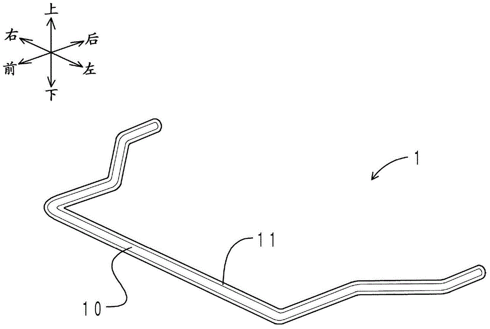
[0044] First, the structure of the stabilizer bar painted using the painting method of this embodiment is demonstrated. figure 1 It is a perspective view showing the balance bar of this embodiment. figure 1 In , the left and right directions are defined based on the state in which the front is viewed from the rear. in addition, figure 1 Represented as a perspective gimbal body.
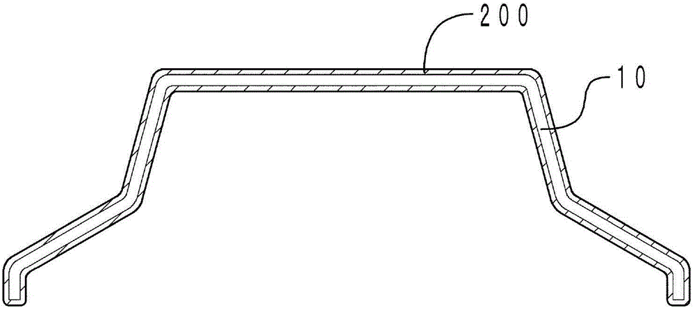
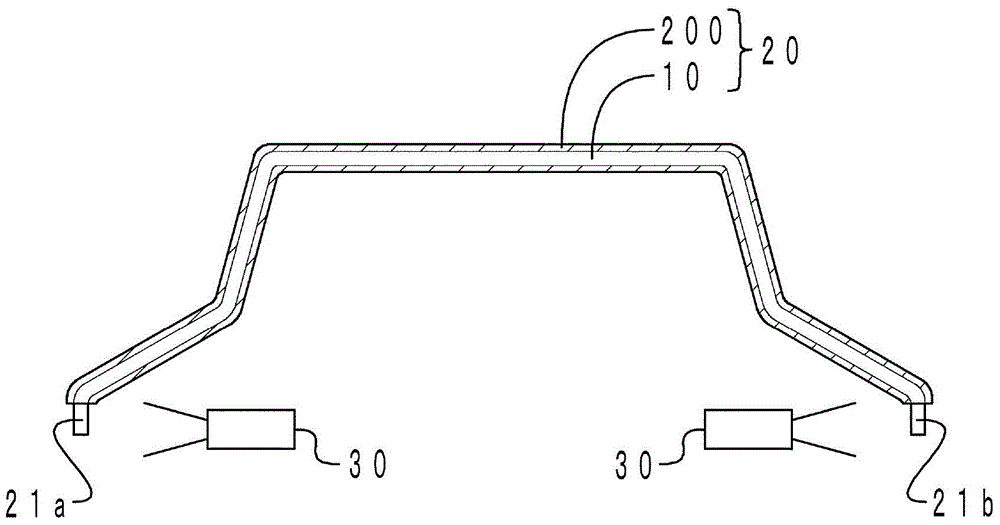
[0045] Such as figure 1 As shown, the stabilizer bar 1 includes a stabilizer bar body 10 and a coating film 11 . The stabilizer main body 10 is made of a carbon steel pipe (STKM13A, outer diameter φ23mm, wall thickness 6mm), and is in the shape of a tube that bulges forward in a C-shape. The stabilizer main body 10 is included in the spring member of the present invention. The coating film 11 covers the surface of the stabilizer main body 10 . The coating film 11 can be epoxy resin / polyester resin powder coating. Epoxy resin / polyester resin powder coatin...
no. 2 approach
[0061] The difference between the coating method of the spring member of the present embodiment and the method of coating the spring member of the first embodiment is that, in the coating process, an epoxy resin-based powder coating is used; and a cover member is used to form a non-coating portion ; and no partial painting process. Therefore, only the points of difference are described here.
[0062] The coating method of the stabilizer main body 10 of this embodiment includes a coating process, an electrode connection process, and a baking process. Image 6 It is a front view showing the main body of the stabilizer before painting in which the cover member is arranged in the painting process. Figure 7 It shows the front view of the main body of the stabilizer with cover parts arranged and painted in the same process. Figure 8 It shows the front view of the stabilizer main body where the non-painted part is formed in the same process. Figure 9 It shows the front view of ...
no. 3 approach
[0067] The difference between the method of coating a spring member of this embodiment and the method of coating a spring member of the second embodiment is that a part of the coating process is performed after the baking process. Therefore, only the points of difference are described here.
[0068] The coating method of the stabilizer main body 10 of this embodiment includes a coating process, an electrode connection process, a baking process, and a partial coating process. From the coating process to the baking process, it is the same as that of the second embodiment. Therefore, description is omitted here. Figure 10 Represented as a front view of the main body of the stabilizer bar in a partial painting process. For illustrative purposes, Figure 10 Represented as a perspective gimbal body. In addition, the hardened coating film is shown by hatching right down.
[0069] Such as Figure 10 As shown, on the surface of the stabilizer bar 10, the uncured coating film 202...
PUM
| Property | Measurement | Unit |
|---|---|---|
| Thickness | aaaaa | aaaaa |
| The average particle size | aaaaa | aaaaa |
Abstract
Description
Claims
Application Information
 - R&D
- Intellectual Property
- Life Sciences
- Materials
- Tech Scout
- Unparalleled Data Quality
- Higher Quality Content
- 60% Fewer Hallucinations
Browse by: Latest US Patents, China's latest patents, Technical Efficacy Thesaurus, Application Domain, Technology Topic, Popular Technical Reports.
© 2025 PatSnap. All rights reserved.Legal|Privacy policy|Modern Slavery Act Transparency Statement|Sitemap|About US| Contact US: help@patsnap.com


