Die pressing mechanism of powder forming machine
A powder molding machine and compression molding technology, which is applied in the direction of material forming presses, presses, manufacturing tools, etc., can solve problems such as unsatisfactory pressurization effects, and achieve high yield, high processing efficiency, and extrusion effects. Good results
- Summary
- Abstract
- Description
- Claims
- Application Information
AI Technical Summary
Problems solved by technology
Method used
Image
Examples
Embodiment 1
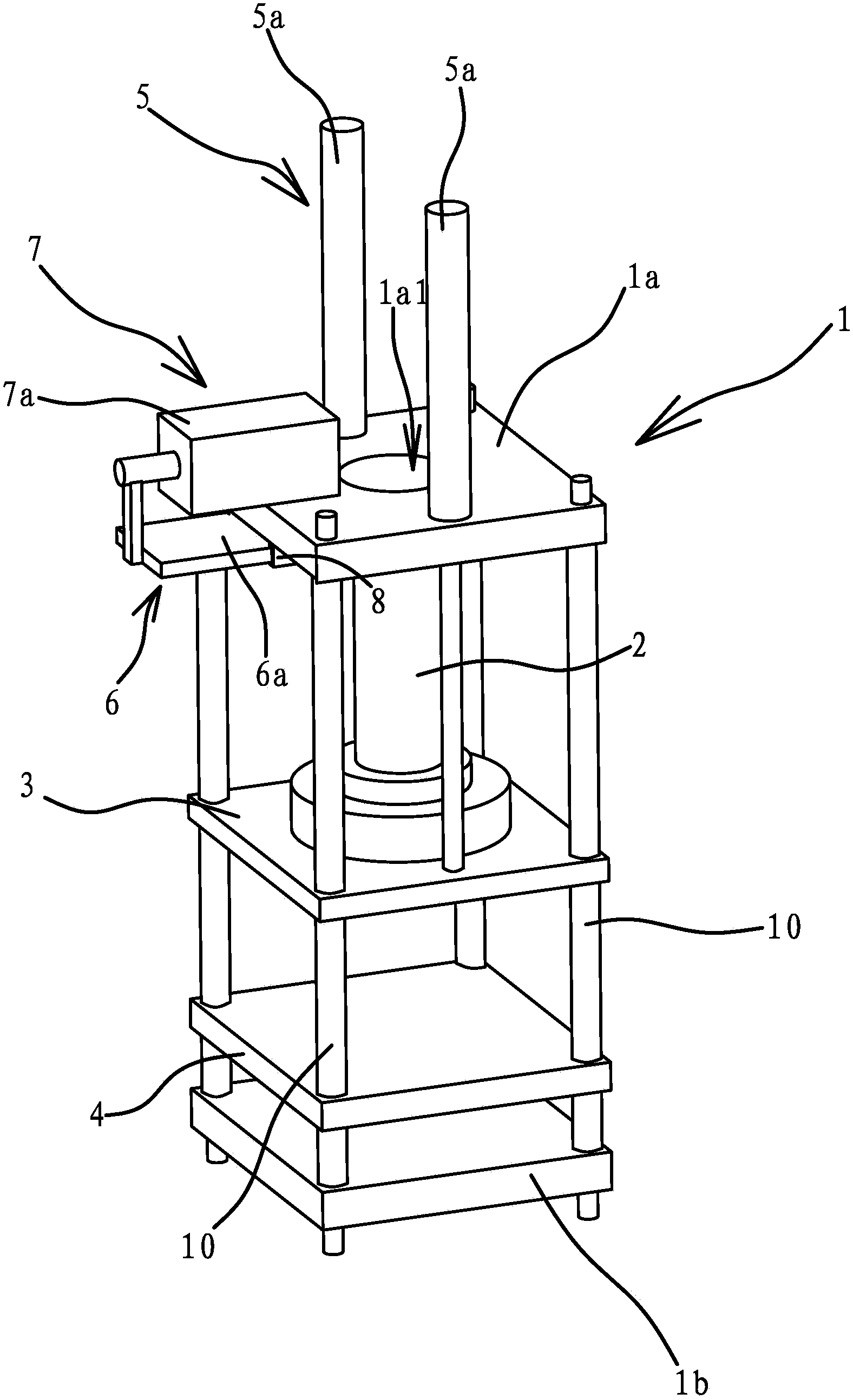
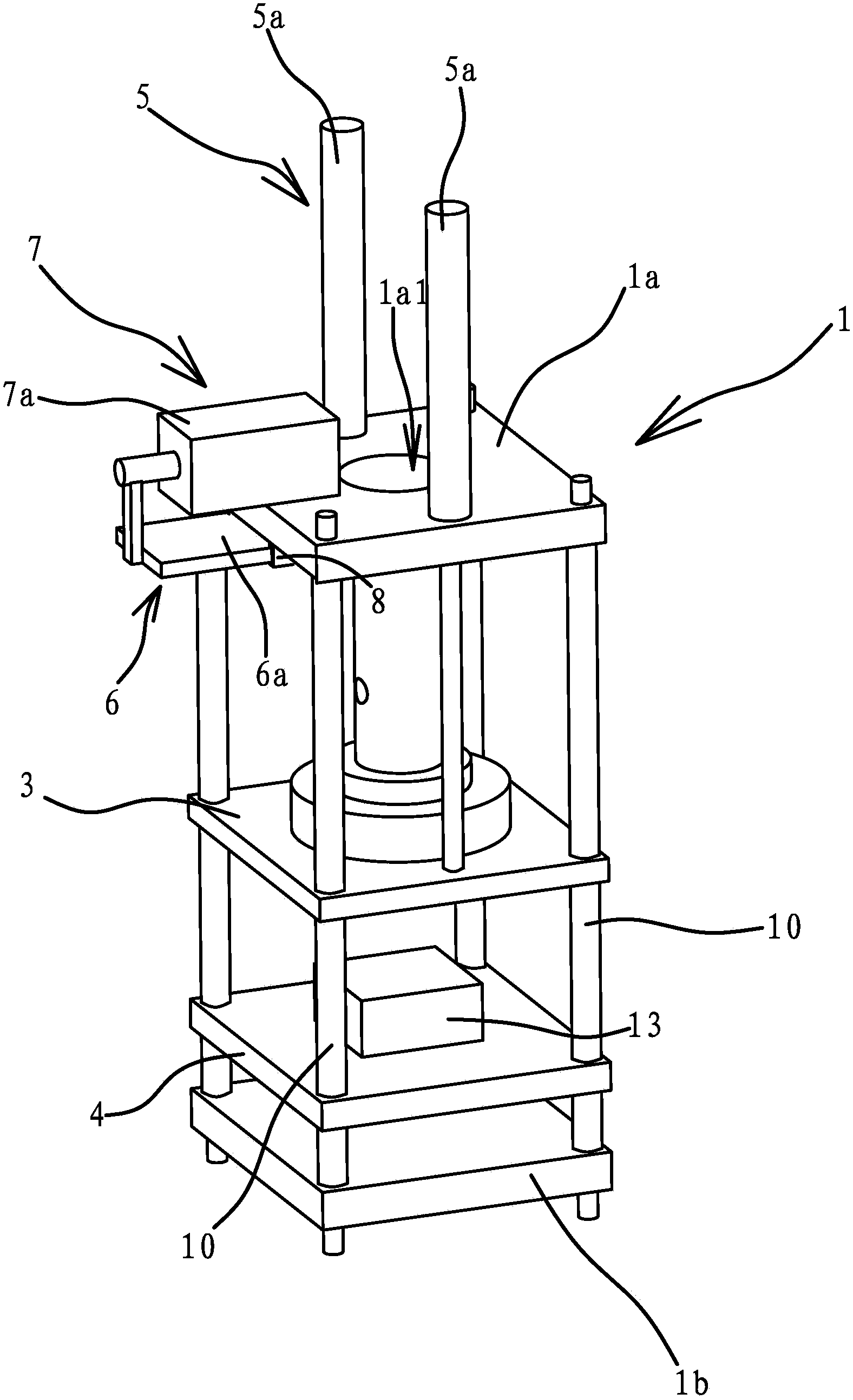
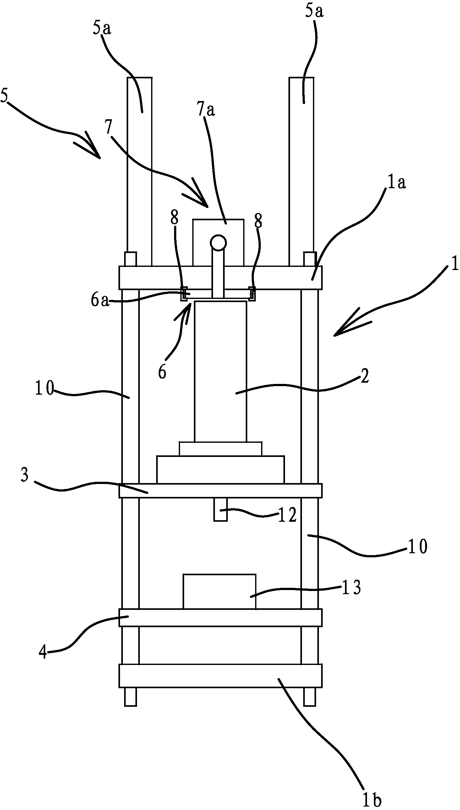
[0038] Such as Figures 1 to 5 As shown, the molding mechanism of the powder molding machine includes a frame 1 and a booster cylinder 2. The frame 1 includes an upper fixed plate 1a and a lower fixed plate 1b parallel to and opposite to the upper fixed plate 1a, an upper template 3 and a lower template 4 for positioning the mold 13 are arranged between the upper fixed plate 1a and the lower fixed plate 1b , there are four guide posts 10 between the upper fixed plate 1a and the lower fixed plate 1b, and the two ends of the guide posts 10 are fixedly connected with the upper fixed plate 1a and the lower fixed plate 1b respectively, and the guide posts 10 pass through the upper formwork 3. The guide pillars 10 all pass through the upper template 3, so that the lifting of the upper template 3 has a better guiding effect. As another way, the lower template 4 and the lower fixing plate 1b adopt an integral structure. The number of guide pillars 10 can be 2 or 6.
[0039] The cyl...
Embodiment 2
[0045] The structure and principle of this embodiment are basically the same as that of Embodiment 1, the difference is that: Figure 6 As shown, the blocking member 6 is a blocking rod 6b arranged parallel to the upper fixing plate 1a, the blocking rod 6b is located on the lower side of the through hole 1a1, one end of the blocking rod 6b is hinged on the upper fixing plate 1a and the blocking rod 6b can rotate horizontally . The driving mechanism 7 is a cylinder 7a whose cylinder body is hinged on the upper fixed plate 1a. The piston rod of the cylinder 7a is arranged horizontally, and the piston rod of the cylinder 7a is hinged with the other end of the stop rod 6b. The blocking rod 6b is driven to rotate by the cylinder 7a to realize the blocking of the upper end of the cylinder body of the pressurized oil cylinder 2, which has the advantage of simple structure and convenient blocking.
Embodiment 3
[0047] The structure and principle of this embodiment are basically the same as that of Embodiment 1, the difference is that: Figure 7 As shown, the upper end of the cylinder body of the pressurized oil cylinder 2 is vertically provided with a bar-shaped retaining post 11, the bar-shaped retaining post 11 passes through the through hole 1a1, the bar-shaped retaining post 11 can abut against the blocking member 6, and the pressurized oil cylinder 2 The upper end of the cylinder block is fixedly connected with a bar-shaped retaining column 11, so that when the upper template 3 is lowered for a larger displacement, the stopper 6 can lean against the bar-shaped retaining column 11 to realize the positioning of the cylinder body of the pressurized oil cylinder 2.
PUM
 Abstract
Description
Claims
Application Information
 - R&D
- Intellectual Property
- Life Sciences
- Materials
- Tech Scout
- Unparalleled Data Quality
- Higher Quality Content
- 60% Fewer Hallucinations
Browse by: Latest US Patents, China's latest patents, Technical Efficacy Thesaurus, Application Domain, Technology Topic, Popular Technical Reports.
© 2025 PatSnap. All rights reserved.Legal|Privacy policy|Modern Slavery Act Transparency Statement|Sitemap|About US| Contact US: help@patsnap.com


