Supercharge Your Innovation With Domain-Expert AI Agents!

Box structure for carrying load and method of making the same

A box-type, load-bearing technology, applied in multi-layer structures, building construction, applications, etc., can solve problems such as increasing the number of rib and fastener attachment parts, and compromising the efficiency of composite assemblies

Active Publication Date: 2014-08-06
THE BOEING CO
View PDF4 Cites 14 Cited by
  • Summary
  • Abstract
  • Description
  • Claims
  • Application Information

AI Technical Summary

Problems solved by technology

However, such an approach may compromise the efficiency of those composite components and may significantly increase the part count for the attachment of ribs and fasteners in order to maintain the stability of the composite aircraft transport wing and stabilizer box structure

Method used


Image

  • Box structure for carrying load and method of making the same
  • Box structure for carrying load and method of making the same
  • Box structure for carrying load and method of making the same

Examples


Embodiment Construction

[0046] The disclosed embodiments will be described more fully hereinafter with reference to the accompanying drawings, in which some, but not all disclosed embodiments are shown. Indeed, several different embodiments may be provided and should not be construed as limited to the embodiments set forth herein. Rather, these embodiments are provided so that this disclosure will be thorough and fully convey the scope of the invention to those skilled in the art.

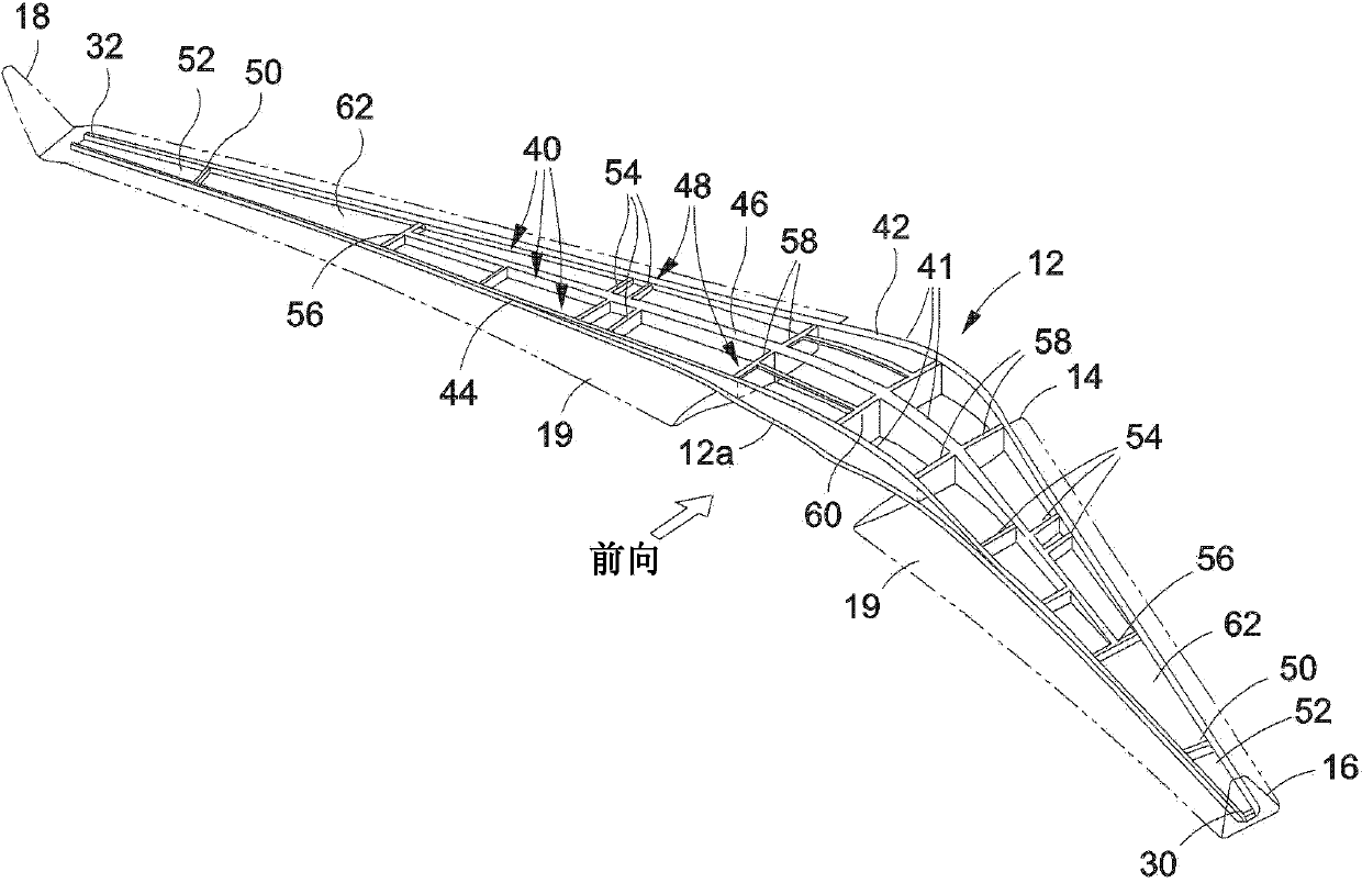
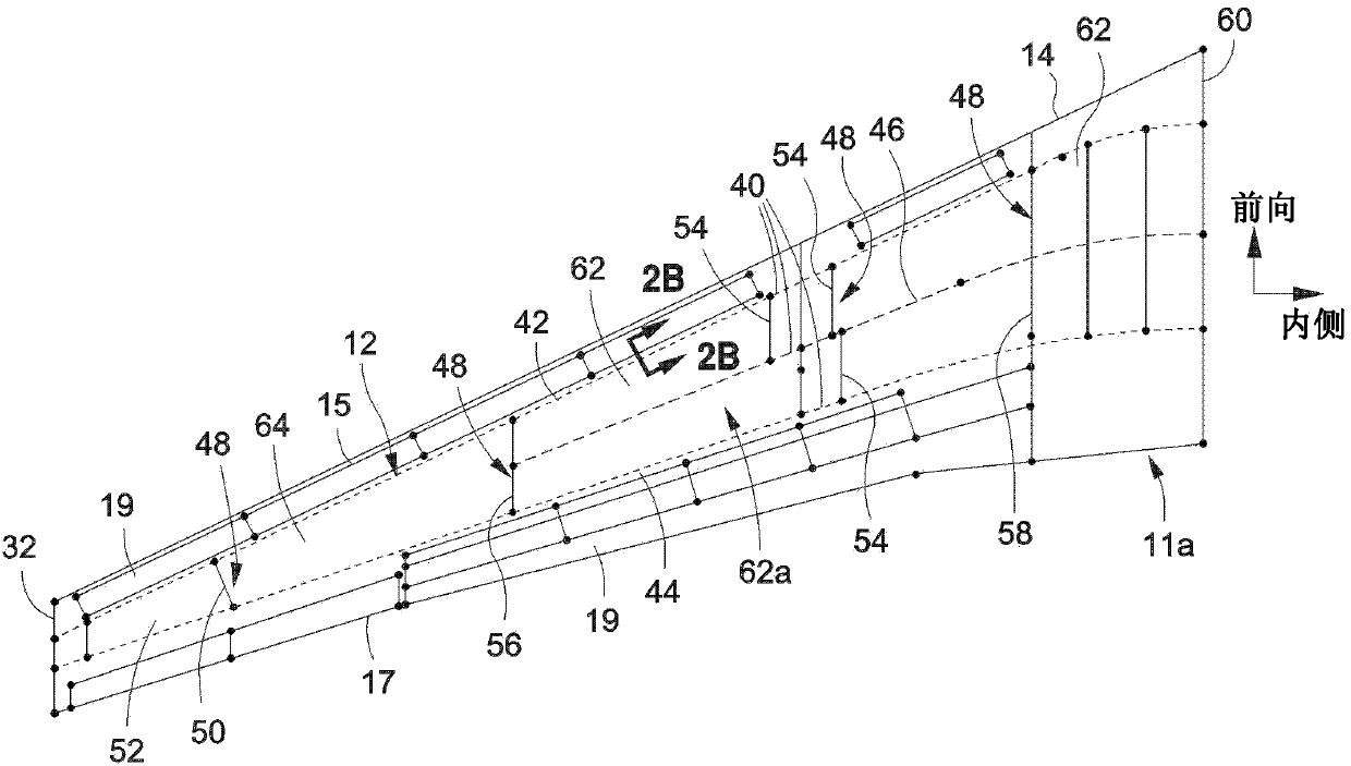
[0047] Referring now to the accompanying drawings, Figure 1A is comprised of one of the method 300 embodiments of the present invention (see Figure 13 ) is an illustration of a perspective view of an air vehicle 10 (eg, an airplane) of an embodiment of a box structure 12 fabricated or machined. Such as Figure 1A As shown, aircraft 10 includes a transport wing structure 13 having an airfoil frame 14 . The airfoil frame 14 includes a leading edge 15 , a first tip 16 , a trailing edge 17 , a second tip 18 and a pluralit...


PUM


Abstract

The invention relates to a box structure for carrying load and a method of making the same. There is provided a box structure for carrying load having upper and lower composite integrated sandwich panels. The panels have facesheets sandwiching one or more core portions and adjacent dense packs oriented in an axial direction. The box structure further has a plurality of spars. Each spar has a web and web attachments and has a spar length in the axial direction. The plurality of spars are connected to the panels with the web attachments located at the dense packs. The facesheets are configured to carry primarily torsion and pressure loads in shear and no significant axial loads. The dense packs are configured to carry all significant box bending in axial tension and compression loads.

Description

technical field [0001] The present invention relates generally to load bearing box structures and methods of manufacture, and more particularly to composite bonded box structures for vehicles and building structures and methods of manufacture. Background technique [0002] Due to their high strength-to-weight ratio, corrosion resistance, and other favorable properties, composite structures (e.g., carbon fiber reinforced plastic (CFRP) composite structures) are widely used in a variety of applications, including for the manufacture of aircraft, spacecraft, rotor Airplanes, automobiles, boats and other vehicles and structures. For example, in aircraft configuration, a large number of composite structures are used to form wings, tails, fuselages, and other components. [0003] Existing composite aircraft transport wing and stabilizer box structures may utilize integral stiffened panel structures consisting of outer composite wing skin panels (ie, "skins") mechanically connecte...

Claims


Application Information

Patent Timeline
Patent Type & Authority Applications(China)
IPC IPC(8): B64C1/08
CPCB29D99/0014B29C70/30B64C3/20B32B5/022B32B5/024B32B5/12B32B5/18B32B3/12B32B2260/023B32B2260/046B32B2262/0261B32B2262/0269B32B2262/101B32B2262/106B32B2266/08B32B2307/54B32B2307/542B32B2307/718B32B2605/18B64C3/185Y02E10/72Y02T50/40E05B63/22E05C1/16
Inventor J·L·马科P·S·努德曼S·T·布朗W·G·罗埃斯埃莱尔T·K·伊索穆拉W·N·韦斯特雷
Owner THE BOEING CO
Features
  • R&D
  • Intellectual Property
  • Life Sciences
  • Materials
  • Tech Scout
  • Unparalleled Data Quality
  • Higher Quality Content
  • 60% Fewer Hallucinations
Learn More