Water pump cavitation testing method and device

A cavitation test and water pump technology, applied in pump control, non-variable pumps, machines/engines, etc., can solve the problems of low test accuracy, long test period, and cumbersome operation

Active Publication Date: 2014-08-06
ZHEJIANG UNIV
View PDF6 Cites 19 Cited by
  • Summary
  • Abstract
  • Description
  • Claims
  • Application Information

AI Technical Summary

Problems solved by technology

[0004] The present invention aims at the problems of cumbersome operation, low test accuracy and long test cycle of the water pump cavitation test method in the current engineering pract

Method used


Image

  • Water pump cavitation testing method and device
  • Water pump cavitation testing method and device
  • Water pump cavitation testing method and device

Examples


Embodiment Construction

[0041] The present invention will be further described in detail with reference to the accompanying drawings and embodiments.

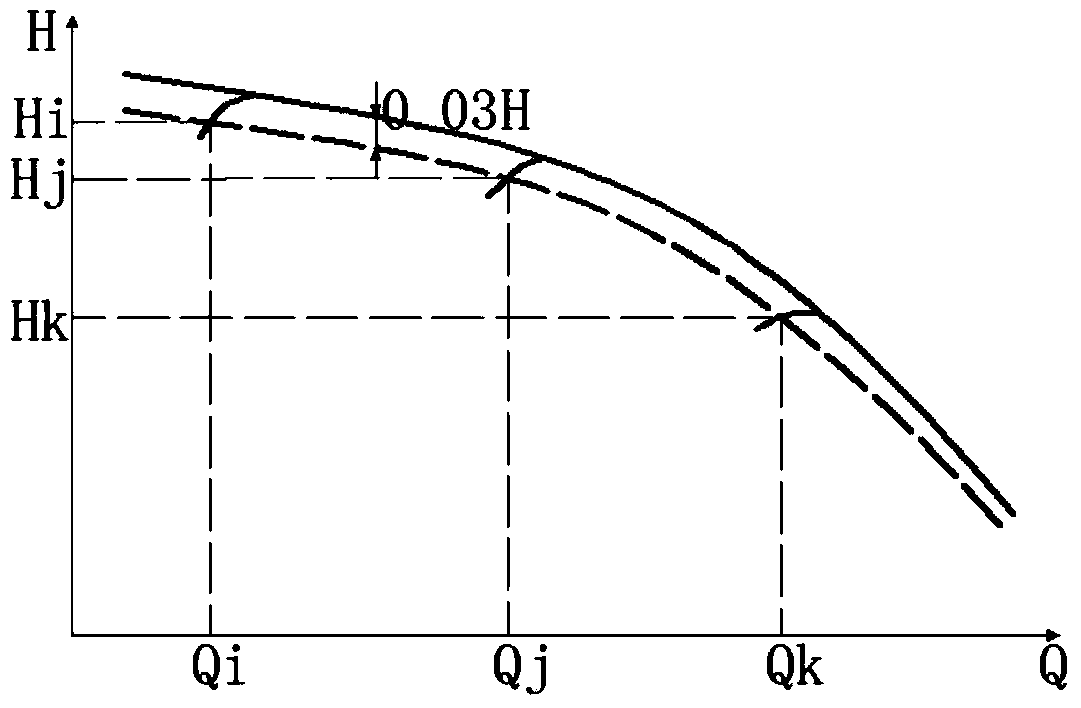
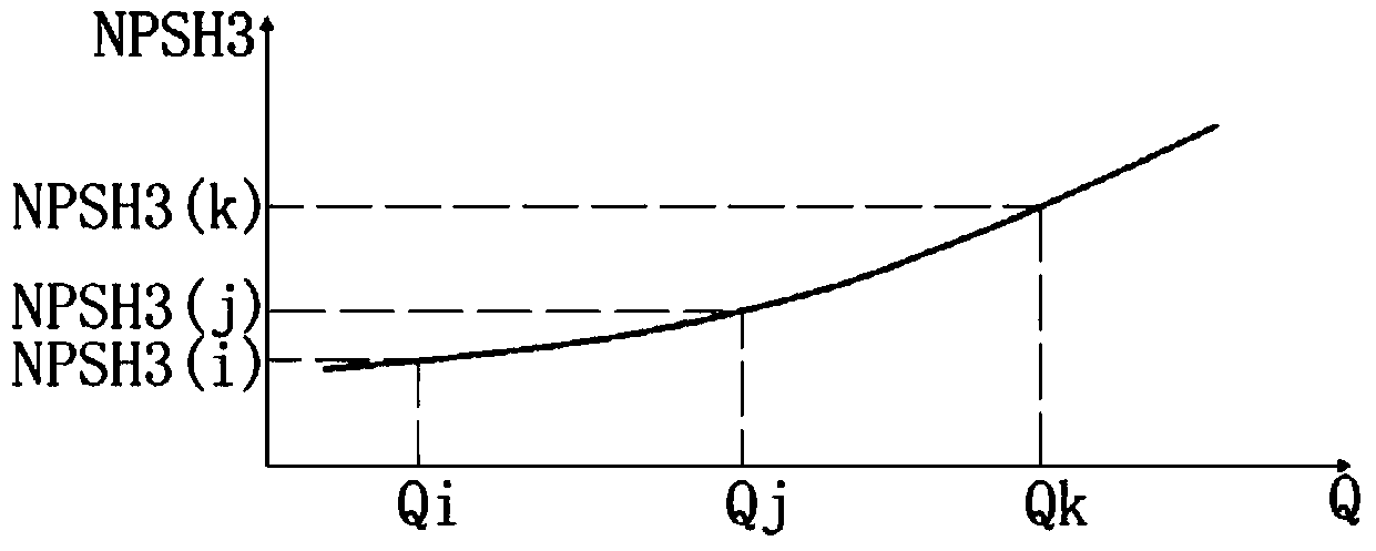
[0042] The NPSH of the pump (NPSHr) indicates the pressure drop during the liquid flow between the pump inlet and the lowest pressure point on the back of the impeller, that is, in order to ensure that the pump does not suffer from cavitation, it is required that the unit weight of the liquid at the pump inlet must have more than the working pressure. The surplus capacity of the vaporization pressure of the liquid at the temperature; the NPSH (NPSHa) of the device is provided by the suction piping system, which means that the unit weight of the liquid at the inlet of the pump actually has a surplus capacity exceeding the vaporization pressure of the liquid at the working temperature . During the actual operation of the pump, when NPSHa≤NPSHr, the pump will experience cavitation. Usually, the state when NPSHa=NPSHr is established is regarded as the cri...


PUM


Abstract

The invention discloses a water pump cavitation testing method. Curve fitting is conducted through pump automation measurement and control system software, a pump performance curve is obtained, and then a corresponding full-condition cavitation distinguishing curve is obtained; starting from a small-flow operating point, pump operating conditions are adjusted to corresponding operating points, pump inlet conditions are initialized, test data are compared with performance test data, and after the requirement for repeatability is met, a cavitation test is started, and the test data are recorded; next, the pump inlet conditions are changed, test data points are recorded in real time, and a test curve is subjected to fitting; whether cavitation happens under indefinite conditions is judged, wherein if cavitation happens, an actual cavitation operating point and cavitation data under the condition are obtained through a graphing method, and the cavitation test is carried out at the next operating point; after the cavitation test is completed, a pump flow-NPSH curve is obtained, and then the cavitation data of the operating point which needs determining are obtained through the graphing method. The invention further discloses a water pump cavitation testing device.

Description

technical field [0001] The invention belongs to the field of water pump cavitation performance test, in particular to a water pump cavitation test method and device. Background technique [0002] During the operation of the pump, at the local low pressure in the impeller flow channel (usually located somewhere behind the inlet on the back of the impeller), the absolute pressure of the delivered liquid is lower than the saturated vapor pressure of the liquid at the temperature for some reason, so that This causes the liquid to vaporize, and a large number of microbubbles grow explosively. The microbubbles rapidly grow into large bubbles and collapse with the liquid flow to the high pressure in the pump, which impacts the wall surface of the flow channel up to hundreds of atmospheres, resulting in the denudation of the wall surface material of the flow channel. This phenomenon is called cavitation. When cavitation occurs, a large number of bubbles "block" the flow channel, ch...

Claims


Application Information

Patent Timeline
IPC IPC(8): F04D15/00
Inventor 吴大转吴俊杨帅
Owner ZHEJIANG UNIV
Why Eureka
Try Eureka