A method and device for estimating the position of a moving target based on time series pseudorange difference

A pseudo-range difference and moving target technology, applied in the field of positioning and navigation, navigation and positioning, can solve the problems of adding devices, poor measurement accuracy, and increased difficulties, and achieve the goals of reducing cumulative errors, improving measurement accuracy, and high position calculation accuracy Effect

Active Publication Date: 2016-10-19
施浒立
View PDF5 Cites 0 Cited by
  • Summary
  • Abstract
  • Description
  • Claims
  • Application Information

AI Technical Summary

Problems solved by technology

However, when it is necessary to solve the positioning and navigation of people in indoor and outdoor travel, especially when it is necessary to solve the positioning and navigation of people in indoor travel, the difficulties encountered increase.
The first is to solve the problem of measuring the step distance. One solution is to use a pedometer, but the pedometer is too large in size, heavy in weight, and the calculation accuracy of the step distance is also poor; another solution is to use an accelerometer to measure Acceleration is obtained, speed is obtained by integrating the acceleration, and then the step distance is measured
This will not only increase the number of devices, but also cause poor measurement accuracy and large errors when traveling at low speeds.

Method used


Image

  • A method and device for estimating the position of a moving target based on time series pseudorange difference
  • A method and device for estimating the position of a moving target based on time series pseudorange difference
  • A method and device for estimating the position of a moving target based on time series pseudorange difference

Examples


Embodiment 1

[0060] Example 1: Timing Pseudorange Difference Simulation Calculation

[0061] 1), the purpose of simulation

[0062] In order to verify the principle and performance of the time-series pseudo-range difference method, simulation calculations are carried out using the measured satellite and user coordinate data.

[0063] 2), simulation steps

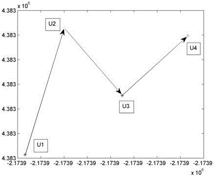
[0064] (1). Four user points were selected in the actual measurement, as shown in the attached Figure 15 shown. The user travels from U1 location to U2, U3, U4 respectively. After coordinate projection, it can be calculated that the azimuth angles of the three true north directions between U1 and U2, U2 and U3, and U3 and U4 are: 52.43°, 87.90°, and 46.82°, respectively.

[0065] (2). Select a GPS satellite with a suitable elevation angle. Its three-dimensional coordinates at U1, U2, U3, and U4 moments are:

[0066] S1=[6085376.3118885652.92 17967531.59]

[0067] S2=[6085133.37 18885532.38 17967735.53]

[0068] S3=[6084890.44 18...


PUM


Abstract

The invention relates to a method and a device for calculating position of a moving target based on time sequence pseudo-range differential. The method and the device are used for calculating the process step pitch of a user among adjoining time elements by obtaining the difference value between two pseudo-ranges among the adjoining time elements, and calculating the change of the coordinate position and the process track from the known position when a user, for example, a pedestrian or a moving carrier marches forward by the step pitch and the processing direction angle. The equal-length time delay deviation value generated when signals are generated, transmitted and received can be eliminated due to the good dependency of the two pseudo-ranges between the two adjoining time elements when the deviation value between the two pseudo-ranges among the adjoining time elements is obtained; meanwhile, the accumulative error generated during position calculating can be eliminated by the difference value between the two pseudo-ranges among the adjoining time elements, so that the method is high in navigating and positioning precisions. After the method and the device are used, the limitation that the satellite navigation needs four-satellite positioning can be broken through, the satellite positioning principle and algorithm can be provided, and the critical defect that the precision is influenced by the accumulative error during the dead reckoning can be made up.

Description

technical field [0001] The invention relates to the field of navigation and positioning. It is a new method and a new measuring device for measuring the transmission distance by using radio ranging signals to realize seamless indoor and outdoor navigation and positioning. It is widely applicable to the field of navigation and positioning, especially for traveling Positioning and navigation of people, vehicles, ships and other carriers. Background technique [0002] Human beings have long used the position of the stars in the sky to guide the direction, and calculated the distance by measuring the step distance, so as to move towards the destination. Later, due to the needs of navigation, Europeans invented the dead-position extrapolation algorithm during the ship's travel, that is, using gyroscopes and accelerometers to guide the direction and meter, and carry out ship position extrapolation, and it is widely used in ship and aircraft navigation. [0003] The successful dev...

Claims


Application Information

Patent Timeline
Patent Type & Authority Patents(China)
IPC IPC(8): G01C21/14
CPCG01C21/206
Inventor 施浒立刘成
Owner 施浒立
Why Eureka
Try Eureka