Testing device for frictional coefficient of cutter and workpiece under supersonic vibration condition

A technology of ultrasonic vibration and friction coefficient, applied in the direction of measuring devices, mechanical devices, instruments, etc., can solve the problems that cannot be used in conjunction with machine tools, cannot be used to test the friction characteristics of tools and materials, and cannot test the friction characteristics of tools and workpieces. Achieve the effect of reducing manufacturing cost and measuring accurately

Inactive Publication Date: 2014-08-06
CONPROFE TECH GRP CO LTD +1
View PDF4 Cites 17 Cited by
  • Summary
  • Abstract
  • Description
  • Claims
  • Application Information

AI Technical Summary

Problems solved by technology

[0006] 2. High machining accuracy mainly depends on the accuracy of the machine tool used, and the shape and position tolerance of the processed workpiece is almost close to the relevant accuracy of the machine tool;
This test method can only test the friction coefficient between the workpiece material specimen and the tool material specimen under general conditions, and cannot be used to test the friction characteristics between the tool and the material during actual cutting motion
And it cannot be used in conjunction with existing machine tools, let alone test the friction characteristics between the tool and the workpiece under the condition of ultrasonic vibration

Method used


Image

  • Testing device for frictional coefficient of cutter and workpiece under supersonic vibration condition

Examples


Embodiment Construction

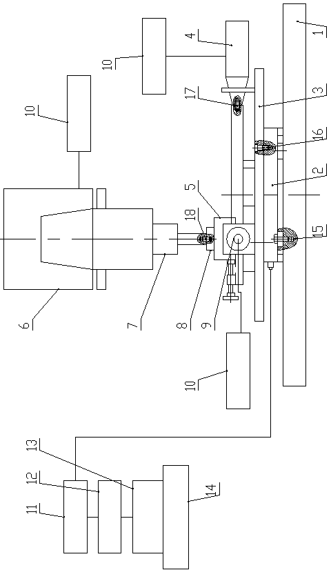
[0034] Such as figure 1Shown, under the ultrasonic vibration condition of the present invention, the friction coefficient testing device between the tool and the workpiece comprises a motion system, an ultrasonic vibration loading system, a measurement system and a data processing system, and the motion system is composed of a machine tool table 1 and a machine tool spindle 6; The loading system is composed of X-direction ultrasonic vibration device 4, Y-direction ultrasonic vibration device 9, Z-direction ultrasonic vibration device 7 and ultrasonic power supply system 10; the measurement system is composed of fixture 3 and piezoelectric three-way dynamometer 2; the data processing system It consists of a charge amplifier 11, a data acquisition device 12, a data analysis system 13 and a computer 14; the piezoelectric three-way dynamometer 2 is fixed on the machine tool workbench 1 by the first bolt 15, and the piezoelectric three-way dynamometer 2 The signal data line is conn...


PUM


Abstract

The invention discloses a testing device for the frictional coefficient of a cutter and a workpiece under a supersonic vibration condition. The testing device comprises a machine tool workbench, a machine tool main shaft, an ultrasonic vibration loading system, a clamp, a piezoelectric three-way resistance dynamometer, a charge amplifier, a data collecting device, a data analysis system and a computer; a cutter material test piece is enabled to apply exert load onto a workpiece material test piece through the moving of the machine tool main shaft, the workpiece material test piece and the cutter material test piece are driven to form friction motion through the motion of the machine tool workbench, the piezoelectric three-way resistance dynamometer detects electrical signals, converts simulating signals into digital signals and then input the digital signals into a computer finally after passing through the charge amplifier, the data collecting device and the data analysis system, and then the friction coefficient of the cutter and the workpiece can be output through software analyzing and calculating. The testing device provided by the invention has the advantages that the accuracy is high, the operation is convenient, conventional machine tool equipment and resistance dynamometers of research organizations can be fully used, and the friction coefficient of samples in different shapes and made of different materials can be tested under different ultrasonic vibration conditions and common processing conditions.

Description

technical field [0001] The invention belongs to the technical field of ultrasonic vibration cutting processing, in particular to a device for testing the friction coefficient between a tool and a workpiece under the condition of ultrasonic vibration. Background technique [0002] Ultrasonic vibration cutting is a special cutting technology that makes the tool vibrate at a high speed along the cutting direction at a frequency of 20-50KHz. [0003] Ultrasonic vibration cutting is a kind of pulse cutting from a microscopic point of view. In a vibration cycle, the effective cutting time of the tool is very short, and the tool is completely separated from the workpiece and chips in more than 80% of the time. The cutting tool is in intermittent contact with the workpiece and chips, which reduces the friction on the cutting tool, greatly reduces the heat generated, and significantly reduces the cutting force, avoiding the phenomenon of "giving way" during ordinary cutting, and doe...

Claims


Application Information

Patent Timeline
Patent Type & Authority Applications(China)
IPC IPC(8): G01N19/02
Inventor 向道辉赵波赵明利马国锋张玉龙高国富焦锋赵重阳王晓博童景琳
Owner CONPROFE TECH GRP CO LTD
Why Eureka
Try Eureka