Bistatic MIMO radar target sparsity imaging method

A technology for sparse imaging and radar targets, applied in radio wave reflection/re-radiation, using re-radiation, measurement devices, etc., can solve the problems of large array amplitude errors, inability to accurately detect targets and imaging, etc.

Inactive Publication Date: 2014-08-06
XIDIAN UNIV
View PDF3 Cites 23 Cited by
  • Summary
  • Abstract
  • Description
  • Claims
  • Application Information

AI Technical Summary

Problems solved by technology

The invention overcomes the disadvantages of the robust beamforming (RCB) method, which requires a large number of snapshots and the inability to accurately detect the

Method used


Image

  • Bistatic MIMO radar target sparsity imaging method
  • Bistatic MIMO radar target sparsity imaging method
  • Bistatic MIMO radar target sparsity imaging method

Examples


Embodiment Construction

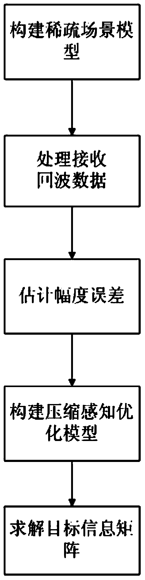
[0055] The present invention will be further described below in conjunction with accompanying drawing:

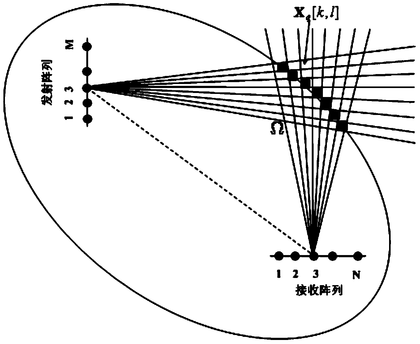
[0056] In the embodiment of the present invention, the bistatic MIMO radar is provided with a transmitting array and a receiving array, wherein the transmitting array adopts an array composed of a uniform linear array, but is not limited to this structure, and the element spacing of the transmitting array is expressed as d t ; The receiving array adopts an array composed of uniform linear arrays, but is not limited to this structure, and the element spacing of the receiving array is expressed as d r ; The wavelength of the transmit signal of the transmit array of the bistatic MIMO radar is denoted as λ. d t and d r The value of d t = d r =λ / 2, but not limited to this value. In the bistatic MIMO radar, the number of array elements in the transmitting array is M, and the number of array elements in the receiving array is N. For example, the number of array elements in th...


PUM


Abstract

The invention belongs to the technical field of bistatic MIMO radar imaging, and particularly relates to a bistatic MIMO radar target sparsity imaging method. The bistatic MIMO radar target sparsity imaging method comprises the following step that target imaging processing is carried out on distance doors of a bistatic MIMO radar in sequence. The target imaging processing carried out on any distance door of the bistatic MIMO radar comprises the steps of constructing a two-dimensional discrete angle space, and converting a target scene into a sparsity scene; then obtaining a receiving signal model obtained after matched filtering in the sparsity scene; setting a transmitting signal amplitude error opposite angle matrix gamma t and receiving a signal amplitude error opposite angle matrix gamma r of the bistatic MIMO radar; according to the receiving signal model obtained after the matched filtering, constructing a compressed sensing optimization model including the gamma trace constraint, wherein gamma=gamma t kronecker product gamma r; solving the compressed sensing optimization model; according to the solved result, obtaining the position where each target is located, and obtaining position imaging diagrams of all the targets.

Description

technical field [0001] The invention belongs to the technical field of bistatic MIMO radar imaging, and in particular relates to a bistatic MIMO radar target sparse imaging method, which can be used for high-resolution imaging of bistatic MIMO radars with amplitude errors, and is especially suitable for scenes with fewer snapshots and larger amplitude errors object detection and imaging. Background technique [0002] Radar is an indispensable electronic equipment in modern military warfare. Because MIMO radar adopts multiple signal transmission and multiple signal reception at the same time, multiple signals can be separated in time domain, air domain or polarization domain, so it has a processing dimension more High, more fully utilized transceiver aperture, higher angular resolution, effectively improve target RCS (radar cross-sectional area) fluctuations, improve detection performance and target spatial resolution advantages. With the continuous development of radar sign...

Claims


Application Information

Patent Timeline
IPC IPC(8): G01S13/89
CPCG01S13/89G01S7/292G01S13/003
Inventor 李军陈茜茜廖桂生郭一帆吕利
Owner XIDIAN UNIV
Why Eureka
Try Eureka