Saline liquid flow magnetic force power generation device

A power generation device and magnetic technology, applied in the direction of electromechanical devices, electrical components, etc., can solve the problems of low feasibility, inability to generate electricity, and occupying large land resources, etc., and achieve the effect of convenient use

Inactive Publication Date: 2014-08-06
SHANGHAI DIANJI UNIV
View PDF1 Cites 2 Cited by
  • Summary
  • Abstract
  • Description
  • Claims
  • Application Information

AI Technical Summary

Problems solved by technology

[0004] Taking reservoir-type water storage power generation and surge power generation platforms as examples, these types of power generation must first be relatively large-scale power generation, and the feasibility of these power generation forms is not high without a large amount of capital investment. In addition, the current tidal power generation They all require changes in the gravitational potential energy of the tidal level to generate electricity, so they are only suitable for shores that meet special conditions for tidal levels, and cannot generate electricity for a state that is kept below the sea surface. In addition, it occupies a relatively large amount of land resources on the coastline, which is also a disadvantage.

Method used


Image

  • Saline liquid flow magnetic force power generation device
  • Saline liquid flow magnetic force power generation device
  • Saline liquid flow magnetic force power generation device

Examples


Embodiment Construction

[0022] The implementation of the present invention is described below through specific examples and in conjunction with the accompanying drawings, and those skilled in the art can easily understand other advantages and effects of the present invention from the content disclosed in this specification. The present invention can also be implemented or applied through other different specific examples, and various modifications and changes can be made to the details in this specification based on different viewpoints and applications without departing from the spirit of the present invention.

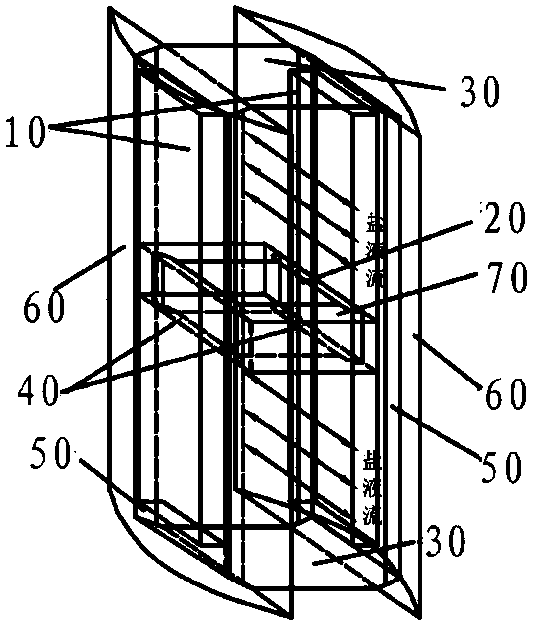
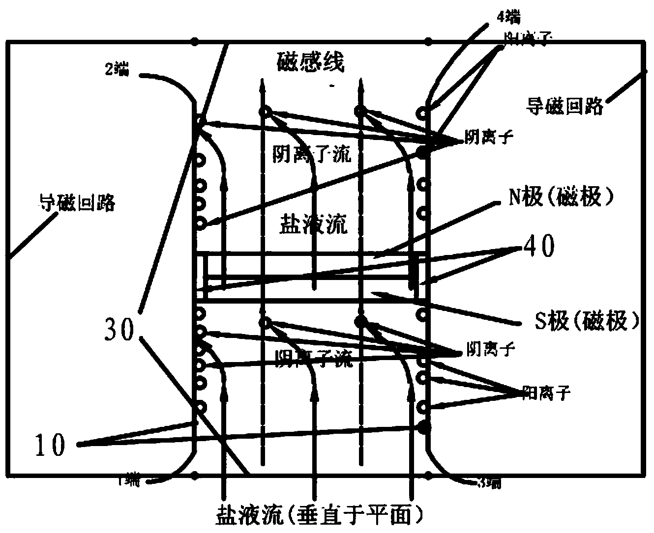
[0023] figure 1 It is a schematic diagram of the outline structure of the basic power generation unit of a kind of salt flow magnetic power generation device of the present invention, as figure 1 As shown, a kind of saline flow magnetic power generation device of the present invention comprises: two conductive plates 10 on the left and right, a magnet 20, two magnetically conductive plates ...


PUM


Abstract

The invention discloses a saline liquid flow magnetic force power generation device. The saline liquid flow magnetic force power generation device comprises a left conductive plates, a right conductive plate, a magnet, an upper magnetism conducting plate, a lower magnetism conducting plate, insulating layers, a left magnetism conducting loop, a right magnetism conducting loop and an insulated shell, wherein the insulating layers are located between the magnetism conducting plates and the magnet. The magnet is located between the left conductive plate and the right conductive plate, the N pole and the S pole of the magnet are located in the directions perpendicular to each other. A perpendicularly upward even magnetic field or a perpendicularly downward even magnetic field is formed by the magnetism conducting plates and the magnet and is located between the conductive plates and the insulated shell, and therefore a low-resistance loop of a magnetic line of force is formed. The saline liquid flow magnetic force power generation device can be installed in any places where saline liquid and water flow exist, so that the power generation range of hydraulic electric generation in a saline water area is expanded; in addition, the structure of the saline liquid flow magnetic force power generation device can be large or small, so that the saline liquid flow magnetic force power generation device is suitable for power generation under various demands in multiple geographical environments.

Description

technical field [0001] The invention relates to a power generating device, in particular to a saline flow magnetic power generating device. Background technique [0002] Because seawater power generation has the advantages of no pollution and no need to consume fuel, how to use ocean energy to generate electricity has become the research goal of ocean engineering researchers all over the world. my country's mainland coastline is more than 18,000 kilometers long, plus various large and small islands, marine energy is very rich. With the increasing tension of renewable energy sources, researching and innovating marine power generation technology is a work of far-reaching significance. [0003] The current ocean energy power generation is typified by ocean tidal energy power generation, of which reservoir-type water storage power generation is the main form of power generation, and other forms of power generation models such as surge power generation platforms are supplemented...

Claims


Application Information

Patent Timeline
Patent Type & Authority Applications(China)
IPC IPC(8): H02K44/00
Inventor 高海凌王嘉毅徐翔平
Owner SHANGHAI DIANJI UNIV
Why Eureka
Try Eureka