Supercharge Your Innovation With Domain-Expert AI Agents!

A Fast Precharge Circuit for Modular Multilevel Converter

A modular multi-level, pre-charging circuit technology, applied in the direction of electrical components, output power conversion devices, etc., can solve the impact of equipment safety and reliability, increase the power loss of current-limiting resistors, and the long time required for pre-charging and other issues, to achieve the effect of improving power utilization, improving work efficiency, and reducing charging time

Active Publication Date: 2016-08-17
SOUTHEAST UNIV
View PDF3 Cites 7 Cited by
  • Summary
  • Abstract
  • Description
  • Claims
  • Application Information

AI Technical Summary

Problems solved by technology

[0004] In the research and application of existing modular multilevel converter pre-charging methods, no matter what kind of pre-charging circuit is used, a current-limiting resistor must be connected in series in the pre-charging circuit, such as figure 1 As shown, in order to prevent the charging current from being too large, when the capacitor voltage rises to the rated value, the current-limiting resistor is short-circuited, but there is only one charging branch and one current-limiting resistor. During the charging process, as the capacitor voltage gradually rises, the charging current will gradually decrease, and the charging speed will also become slower and slower
If it is applied in high-voltage and high-power occasions, such as in the field of high-voltage direct current transmission, the voltage level is very high, and the number of capacitors required to be charged is also large, and the time required for pre-charging is generally very long, which is not only not conducive to the application in engineering practice , and increases the power loss on the current limiting resistor, which also has a great impact on the safety and reliability of the equipment

Method used


Image

  • A Fast Precharge Circuit for Modular Multilevel Converter
  • A Fast Precharge Circuit for Modular Multilevel Converter
  • A Fast Precharge Circuit for Modular Multilevel Converter

Examples


Embodiment Construction

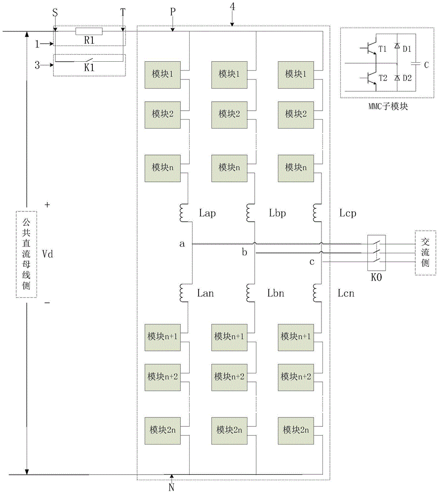
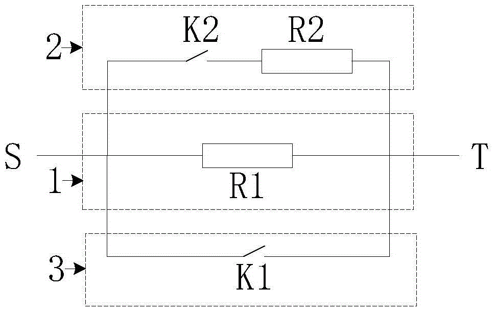
[0023] The fast pre-charging circuit of the modular multi-level converter consists of three parts, including the main current-limiting charging part, the accelerated charging part and the normal operation part.

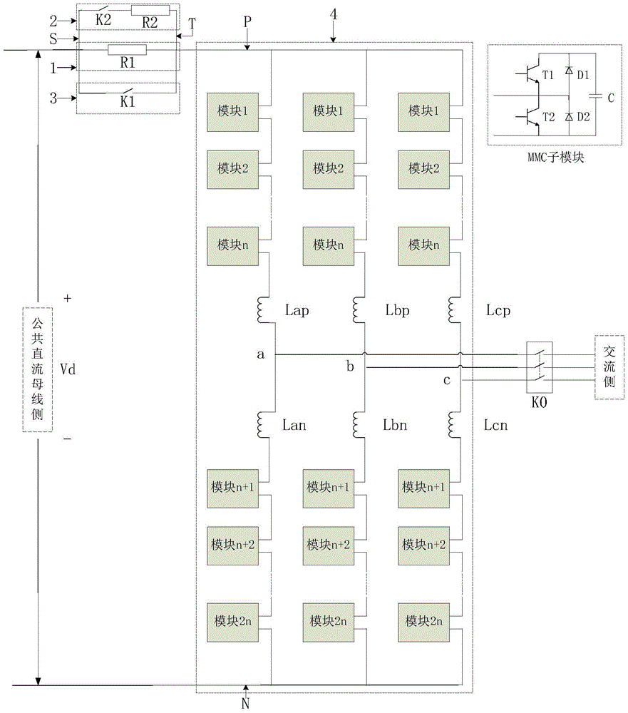
[0024] The charging power source of the fast precharging circuit of the modular multilevel converter can be charged by a DC power supply or an AC power supply. When charging with a DC power source, such as image 3 , the common terminals S and T of the fast precharging circuit are respectively connected to the positive pole of the DC power supply and the common terminal P of the upper bridge arm of the modular multilevel converter. When charging with an AC power source, such as Figure 4 , the fast precharging circuit uses a three-phase AC structure, and is respectively connected to the AC power supply and the common terminals a, b, and c of each phase bridge arm of the modular multilevel converter. The fast pre-charging circuit of the modular multi-level converter ...


PUM


Abstract

The invention provides a rapid precharging circuit for a modular multi-level converter. The rapid precharging circuit comprises a main current-limiting charging portion, an accelerated charging portion and a normal running portion. The main current-limiting portion is a current-limiting resistor. According to the accelerated charging portion, a contactor is in series connection with a current-limiting resistor. The normal running portion is a contactor. The main current-limiting charging portion, the accelerated charging portion and the normal running portion are of a parallel-connection structure. After the parallel connection, one common end is connected with a charging power source, the other common end is connected with the modular multi-level converter, and the charging power source can be a direct-current power source or an alternating-current power source. If charging is carried out with the alternating-current power source, the precharging circuit needs a three-phase alternating-current structure. The rapid precharging circuit for the modular multi-level converter can achieve the charging function of a traditional precharging circuit for the modular multi-level converter, and the circuit is simple in structure and control mode, capable of greatly shortening the charging time and effectively reducing charging losses, and particularly suitable for occasions with high voltage and high power or longer precharging time.

Description

technical field [0001] The invention belongs to the technical field of power electronics applications, and in particular relates to a fast precharging circuit for precharging a modular multilevel converter and its working method. Background technique [0002] With the rapid development of the economy and the gradual expansion of the scale of social production, the demand and consumption of energy are also increasing, the demand for various forms of electricity is constantly increasing, and the requirements for energy saving and consumption reduction of power electronic equipment are also increasing. High, power electronics technology has developed rapidly, among which multilevel converters are gradually becoming high-voltage large converters because of their advantages such as high output voltage, low harmonic content, small voltage change rate, small voltage stress of power switching devices, and low switching frequency. Research hotspots in the field of power electric appl...

Claims


Application Information

Patent Timeline
Patent Type & Authority Patents(China)
IPC IPC(8): H02M1/36
Inventor 赵剑锋李东野
Owner SOUTHEAST UNIV
Features
  • R&D
  • Intellectual Property
  • Life Sciences
  • Materials
  • Tech Scout
  • Unparalleled Data Quality
  • Higher Quality Content
  • 60% Fewer Hallucinations
Learn More