Power transmitting apparatus, power receiving apparatus, and power transmitting system

一种输电装置、受电装置的技术,应用在电路装置、电磁波系统、电池电路装置等方向,能够解决供电单元大型化等问题,达到避免大型化的效果

Inactive Publication Date: 2014-08-06
TOYOTA JIDOSHA KK
View PDF10 Cites 6 Cited by
  • Summary
  • Abstract
  • Description
  • Claims
  • Application Information

AI Technical Summary

Problems solved by technology

As a result, the size of the power supply unit (transmission unit), especially in the height direction, may increase

Method used


Image

  • Power transmitting apparatus, power receiving apparatus, and power transmitting system
  • Power transmitting apparatus, power receiving apparatus, and power transmitting system
  • Power transmitting apparatus, power receiving apparatus, and power transmitting system

Examples


Embodiment approach

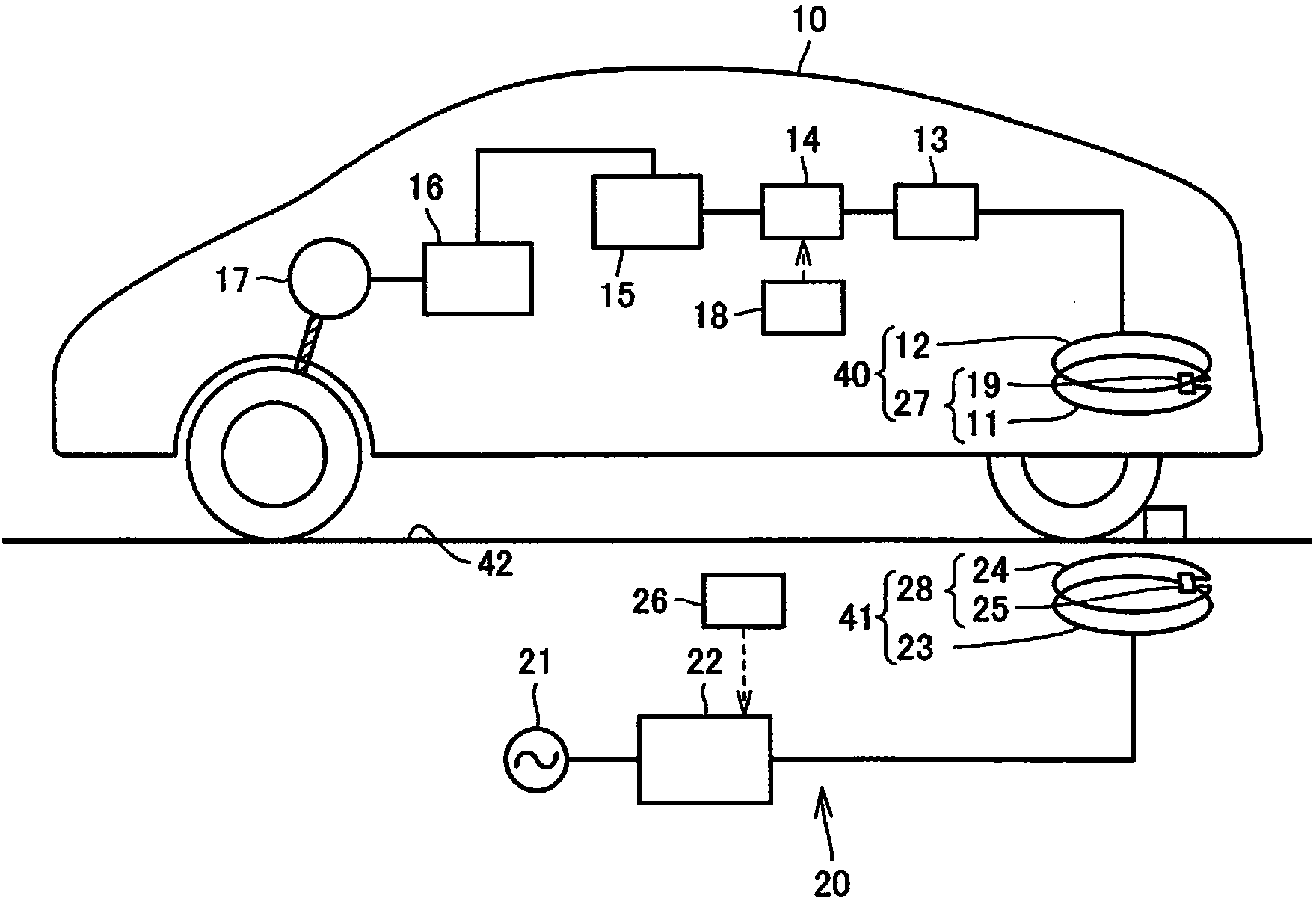
[0061] refer to figure 1 , the power transmission system according to the present invention will be described. figure 1 It is a diagram schematically illustrating a power transmission device, a power reception device, and a power transmission system in this embodiment.

[0062] The power transmission system according to Embodiment 1 includes an electric vehicle 10 including a power receiving device 40 and an external power feeding device 20 including a power transmission device 41 . The power receiving device of the electric vehicle 10 is parked at a predetermined position of the parking space 42 provided with the power transmission device 41 , and mainly receives electric power from the power transmission device 41 .

[0063] The parking space 42 is provided with a wheel stopper or a line indicating a parking position and a parking range so that the electric vehicle 10 is parked at a predetermined position.

[0064] The external power supply device 20 includes: a high-frequ...


PUM


Abstract

A power transmitting apparatus (41) is provided with: a power transmitting unit (28), which transmits power, in a non-contact manner, to a power receiving unit (27) that is provided outside; and a cylindrical power transmitting-side shield (102), which is provided to surround the power transmitting unit (28). On the power transmitting-side shield (102) side, i.e., the reverse side of a region where the power receiving unit (27) is positioned, electromagnetic waves can pass through, and a shield member (103) is provided on the power transmitting-side shield (102) side, i.e., the reverse side of the power transmitting unit (28) with the power transmitting-side shield (102) between the power transmitting-side shield and the shield member.

Description

technical field [0001] The invention relates to a power transmission device, a power receiving device and a power transmission system. Background technique [0002] In recent years, attention has been drawn to hybrid vehicles, electric vehicles, and the like, which drive drive wheels using electric power from batteries or the like due to environmental considerations. [0003] Especially in recent years, in electric vehicles equipped with batteries as described above, wireless charging capable of charging the batteries in a non-contact manner without using a plug or the like has attracted attention. Furthermore, various charging methods have recently been proposed as non-contact charging methods. [0004] As a power transmission system using a non-contact charging method, for example, JP 2010-070048 A (Patent Document 1), JP 2010-252583 A (Patent Document 2), JP 2008 A - Publication No. 294385 (Patent Document 3), Japanese Patent Application Laid-Open No. 2009-004512 (Paten...

Claims


Application Information

Patent Timeline
Patent Type & Authority Applications(China)
IPC IPC(8): H01F38/14H01F27/36H02J17/00H02J7/00
CPCH01F27/36Y02T10/7088H02J5/005B60L11/182Y02T90/14H02J17/00Y02T90/122H02J7/025Y02T10/7005H01F38/14Y02T10/7072B60L53/126H02J50/12H02J50/70Y02T10/70H01F27/363H02J50/005B60L53/12Y02T90/12
Inventor 市川真士
Owner TOYOTA JIDOSHA KK
Why Eureka
Try Eureka