Automatic hose cutting-off device

An automatic cutting and hose technology, which is applied in metal processing and other directions, can solve problems such as difficult speed, affecting production speed, noise pollution in processing environment, etc., and achieves continuous cutting, simple structure, and improved production efficiency.

Active Publication Date: 2014-08-13
南通市通州区三槐机械制造有限公司
View PDF9 Cites 5 Cited by
  • Summary
  • Abstract
  • Description
  • Claims
  • Application Information

AI Technical Summary

Problems solved by technology

Flat cutting needs to squeeze the hose first and then cut it, so that the hose will be squeezed and deformed, which will seriously affect the subsequent use of the hose
Cutting is the cutting of the hose by the blade along the radial direction of the hose. This method is difficult and slow for large-diameter hoses, which affects the production speed.
Circular cutting is to change the

Method used


Image

  • Automatic hose cutting-off device
  • Automatic hose cutting-off device
  • Automatic hose cutting-off device

Examples


Embodiment 1

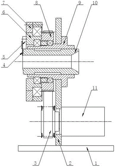
[0026] Such as Figure 1-2 As shown, an automatic hose cutting device includes a support frame, a transmission mechanism, a guide mechanism and a cutting mechanism, wherein: the support frame 1 includes a vertically arranged support plate 2, and a fixed sleeve 9 is worn on the support plate 2. The fixing sleeve 9 is used for the output channel of the extruded hose from the pipe making machine.

[0027] The transmission mechanism includes an inner moving ring 6 rotatably sleeved on the fixed sleeve 9 and an outer moving ring 7 rotatably sleeved on the inner moving ring 6. The transmission mechanism also includes a servo motor 11 fixedly arranged on the support plate 2 and connected to the inner The moving coil 6 drives the synchronous pulley 8 connected to it. The servo motor 11 drives the synchronous pulley 8 to rotate through the synchronous belt 3. The synchronous pulley 8 drives the inner moving coil 6 to rotate around the fixed sleeve 9. At the same time, the inner moving ...

Embodiment 2

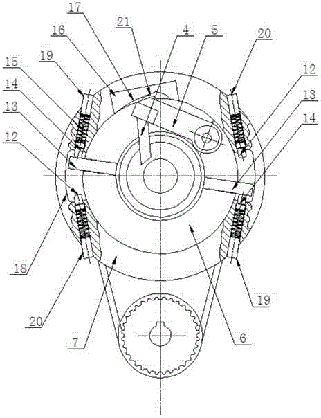
[0035] All the other are identical with embodiment, and difference is, as image 3As shown, in order to ensure the stability of the transmission, the limit bumper 13 of the inner moving coil 6 is symmetrically arranged, and a symmetrical limit groove is arranged on the position corresponding to the limit bumper 13 on the outer moving ring, and the inner moving coil drives When the outer moving coil rotates, the symmetrical use of the limit bumper to contact and drive the limit buffer head in the limit groove will make the device run more smoothly.

Embodiment 3

[0037] The rest are the same as in Embodiment 2, the difference is that a buffer layer is also provided on the outer surfaces of the front limit buffer head and the rear limit buffer head. When the head or the rear limit buffer head contacts, the buffer is further reduced, so that the automatic hose cutting device basically realizes the noiseless operation.


PUM


Abstract

The invention provides an automatic hose cutting-off device. The automatic hose cutting-off device comprises a support frame, a transmission mechanism, a guide mechanism and a cutting-off mechanism; the support frame comprises a supporting plate and a fixed sleeve penetrating through the supporting plate; the transmission mechanism comprises an inner moving coil rotatably sleeving the fixed sleeve and an outer moving coil rotatably sleeving the inner moving coil; the inner moving coil drives the outer moving coil to rotate together by use of a limiting bump fixedly arranged on the inner moving coil; the guide mechanism is fixedly arranged on the outer moving coil and comprises a guide slider; the cutting-off mechanism comprises a blade holder, and a blade fixedly arranged on the blade holder; one end of the blade holder is arranged on and hinged to the inner moving coil and used for enabling the blade to cut a hose back and forth in the radial direction. The automatic hose cutting-off device is capable of eliminating bumping noise while cutting the hose and protecting the hose against deformation during continuous cutting, and applicable to cutting the hoses of various diameters.

Description

technical field [0001] The invention relates to a hose processing equipment, in particular to an automatic hose cutting device for an aluminum-plastic composite hose or an all-plastic hose. Background technique [0002] At present, the cutting of aluminum-plastic composite hose or all-plastic hose mainly includes flat cutting, chopping or round cutting. Flat cutting is to use two knives to squeeze and cut the hose; chopping is to use a blade to cut off the hose in the radial direction; The hose is cut off circumferentially. Flat cutting needs to squeeze the hose first and then cut it, so that the hose will be squeezed and deformed, which will seriously affect the subsequent use of the hose. Cutting is the cutting of the hose by the blade along the radial direction of the hose. This method is difficult and slow for large-diameter hoses, which affects the production speed. Circular cutting is to change the position of the hose by changing the position of the blade due to th...

Claims


Application Information

Patent Timeline
IPC IPC(8): B26D1/06B26D5/08
Inventor 徐惠朝张艳娟
Owner 南通市通州区三槐机械制造有限公司
Why Eureka
Try Eureka